Routing the cables—with two eddy current brakes – Dynojet 424xLC2: Installation Guide User Manual
Page 62
C H A P T E R 3
Cable Routing
Above Ground Model 424x/424xLC
2
Automotive Dynamometer Installation Guide
3-20
R
OUTING
THE
C
ABLES
—W
ITH
T
WO
E
DDY
C
URRENT
B
RAKES
Use the following instructions along with Figure 3-11 on page 3-22 for routing cables
with two eddy current brakes. Refer to Chapter 4 for eddy current brake installation
instructions.
You will need the following parts:
• DM150-009-003 Washer, 1/4", Flat (4)
• DM150-011-005 Bolt, 1/4" x 1/2", Hex (4)
1
Pull both the first and second cable tracks out from under the dyno.
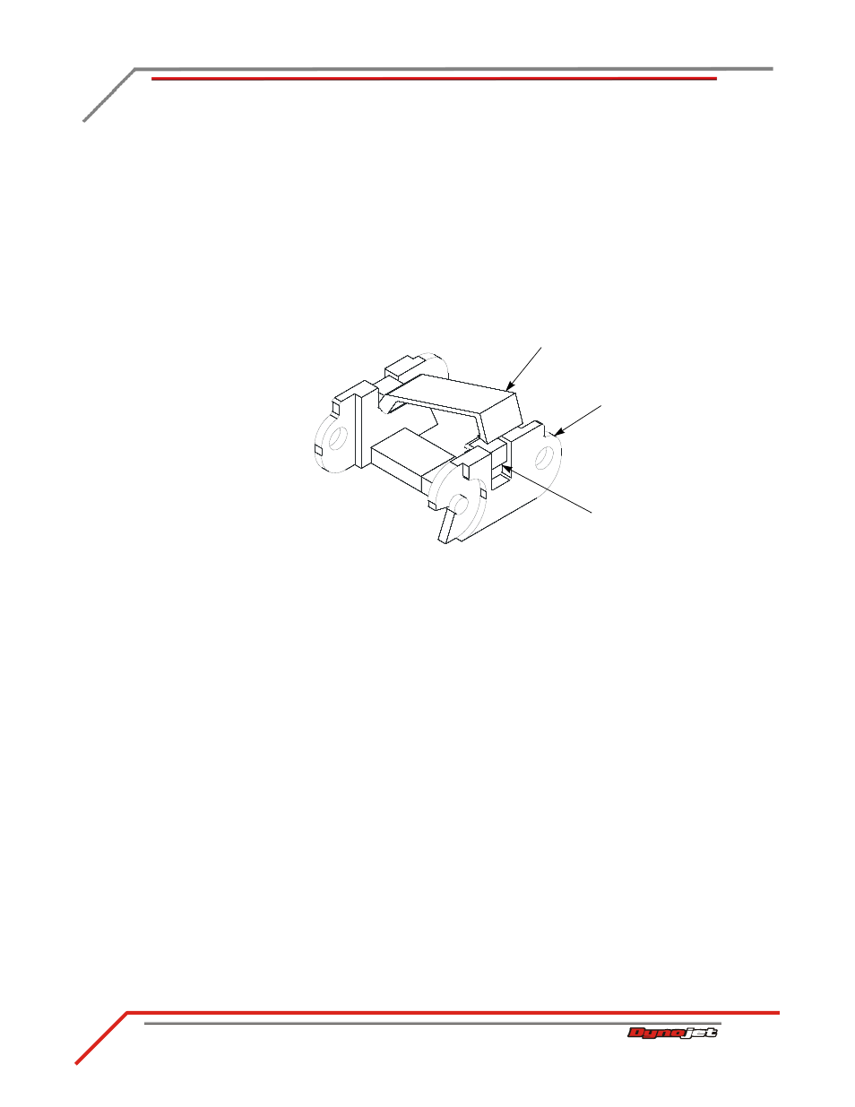
2
Using a screwdriver, open the crossbar on each link.
Figure 3-10: Open the Crossbar
3
Place the eddy current brake driver power cable (I) in the first cable track.
Note: Keep the power cables in a separate cable track from the signal cables.
4
Place the pickup/brake cable (J), the CAN control cable (K), and the air hose (Q)
in the second cable track.
5
Close the cable door on each link.
6
Place the cable tracks back under the dyno.
7
Secure the first and second cable tracks to the front rail tie assembly using two
1/4-20 x 1-inch hex-head screws and two washers each.
8
Route the pickup/brake cable (J) from the speed pickup card and the brake
solenoid leads on the stationary dyno to DRUM 1 on the back of the DynoWare RT
module.
Route the pickup/brake cable (J) from the second cable track to DRUM 2 on the
back of the DynoWare RT module.
9
Route the CAN control cable (K) from the eddy current brake driver on the
stationary dyno to the back of the DynoWare RT module.
Route the CAN control cable (K) from the second cable track to the back of the
DynoWare RT module.
AD079
cable track
link
crossbar
use screwdriver
to open