Dynojet 424xLC2: Installation Guide User Manual
Page 110
C H A P T E R 4
Eddy Current Brake Installation
Above Ground Model 424x/424xLC
2
Automotive Dynamometer Installation Guide
4-14
5
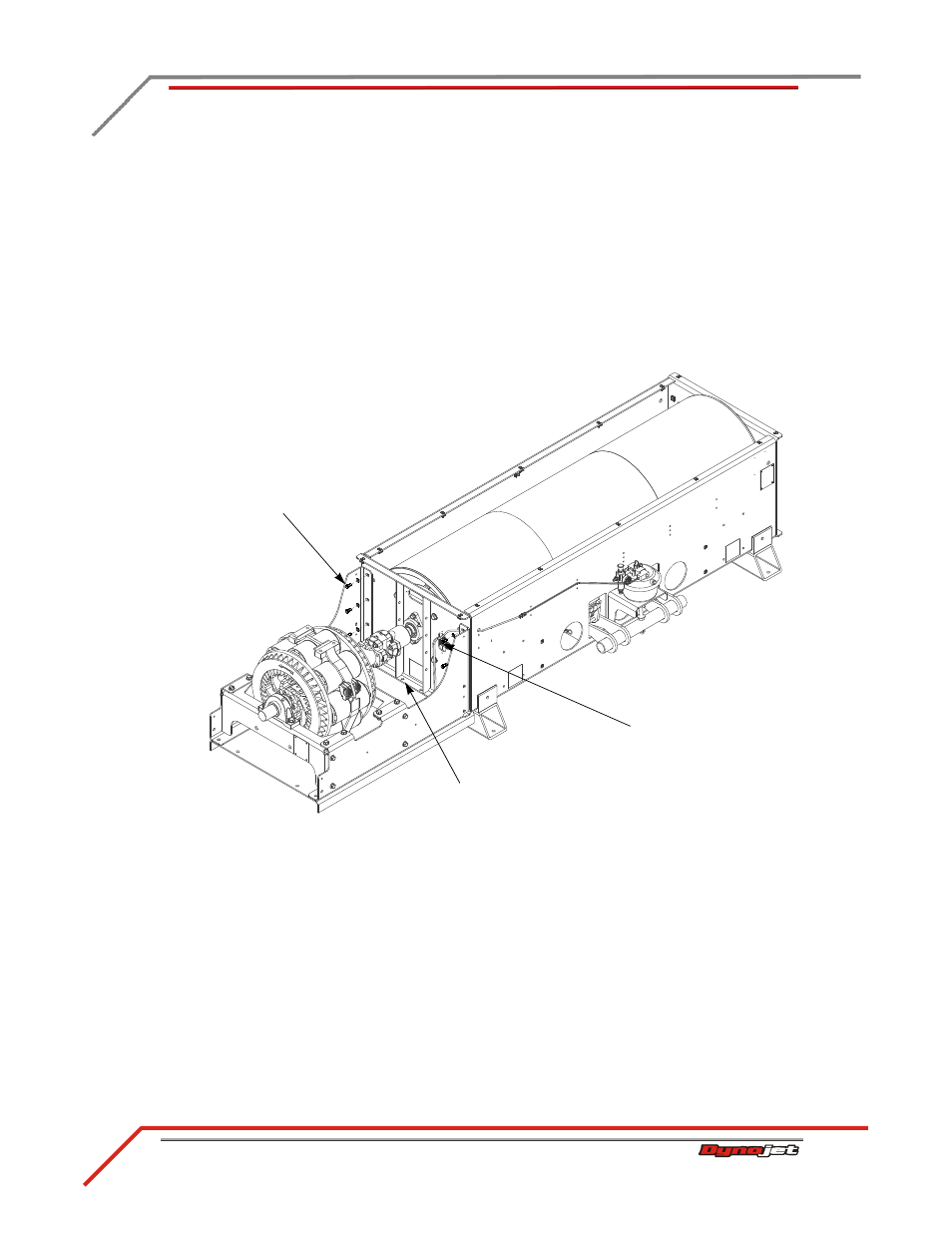
Secure the side of the brake frame to the dyno using eight 3/8-16 x 1-inch hex
bolts and eight 3/8-inch hardened flat washers. Not all of the bolts and washers
are visible from this view.
6
Secure the stiffener plate to the dyno using four 1/2-13 x 1.5-inch flange-hex bolts,
four 1/2-inch flat washers, and four 1/2-13 nylock nuts. Not all of the bolts and
washers are visible from this view.
7
Secure the yoke to the driveline assembly using the four bolts removed earlier.
Torque the bolts to 70 foot-pounds.
8
Torque the brake yoke set screws to 25 foot-pounds.
Figure 4-12: Secure the Brake Frame to the Dyno
EB246
secure brake side to
dyno using bolts and
washers (not all visible)
secure brake side to dyno
using bolts and washers
(not all visible)
secure stiffener plate to
dyno using bolts and
washers (not all visible)