Transmit direction: application to fifo, Data structure – Achronix Speedster22i 10G/40G/100G Ethernet User Manual
Page 33
UG029, September 6, 2013
33
Transmit Direction: Application to FIFO
On transmit, it is the responsibility of the application to monitor the ff_tx_rdy signal. The
user may only transfer data to the transmit FIFO when the ff_tx_rdy signal is high. When
the transmit FIFO deasserts the ff_tx_rdy signal, the user must stop sending data within
the next 8 cycles or the transmit FIFO may overflow. The user may vary the maximum
number of writes allowed after the deassertion of the ff_tx_rdy signal by changing the
threshold value of the transmit FIFO’s ff_tx_rdy almost-full flag.
Data Structure
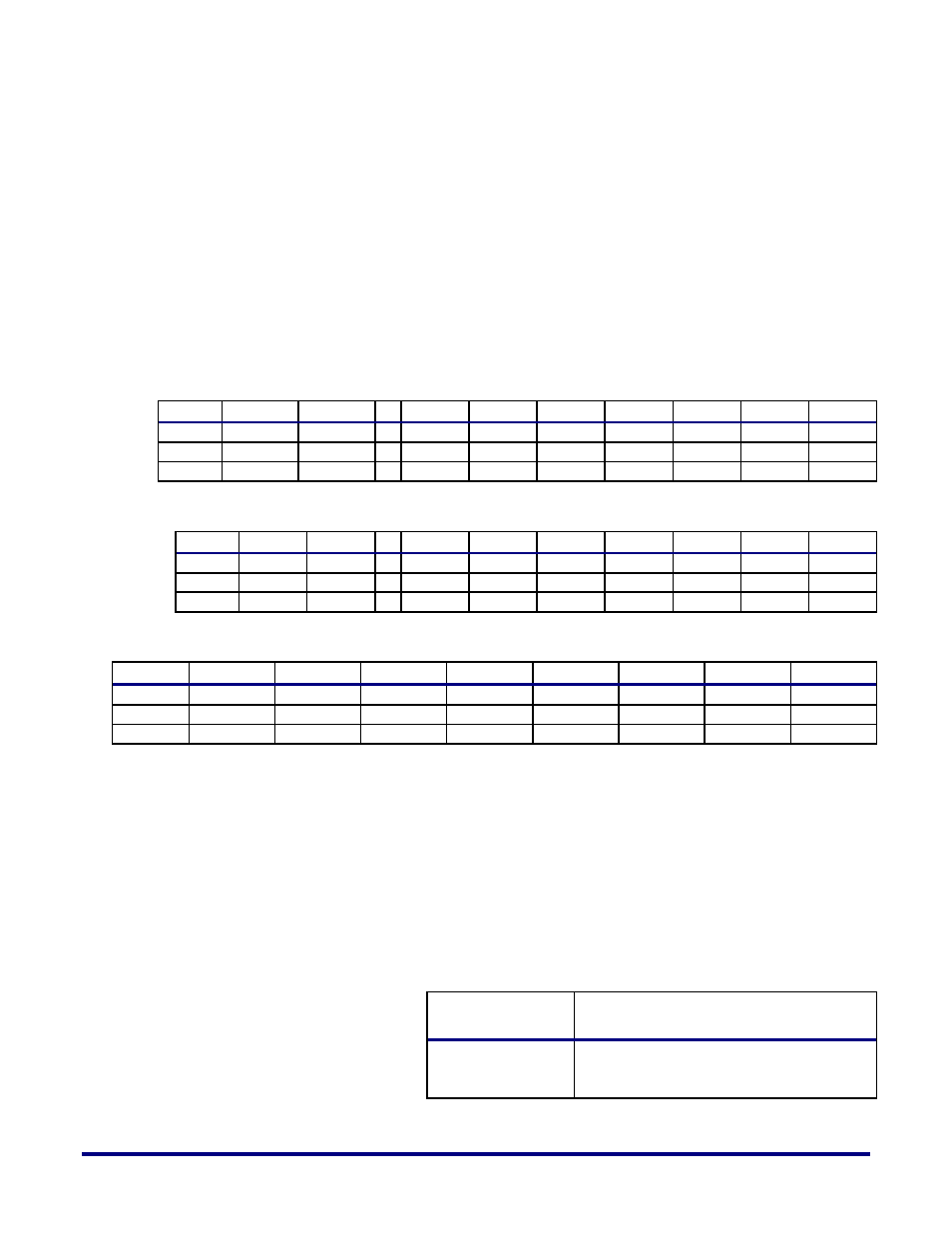
The data structure defined in the following tables for the FIFO interface must be respected to
ensure proper data transmission on the Ethernet line.
Table 14
– 100G FIFO Interface Data Structure
511 504
503 496
…
55 48
47 40
39 32
31 24
23 16
15 8
7 0
word 0
byte 63
byte 62
byte 6
byte 5
byte 4
byte 3
byte 2
byte 1
byte 0
word 1 byte 127 byte 126
byte 70 byte 69 byte 68 byte 67 byte 66 byte 65 byte 64
...
...
...
Table 15
– 40G FIFO Interface Data Structure
255 248
247 240
…
55 48
47 40
39 32
31 24
23 16
15 8
7 0
word 0 byte 31 byte 30
byte 6
byte 5
byte 4
byte 3
byte 2
byte 1
byte 0
word 1 byte 63 byte 62
byte 38 byte 37 byte 36 byte 35 byte 34 byte 33 byte 32
...
...
...
Table 16
– 10G FIFO Interface Data Structure
31 24
23 16
15 8
7 0
31 24
23 16
15 8
7 0
word 0
byte 7
byte 6
byte 5
byte 4
byte 3
byte 2
byte 1
byte 0
word 1
byte 15
byte 14
byte 13
byte 12
byte 11
byte 10
byte 9
byte 8
...
...
...
...
...
Byte 0 is sent and received first to/from the line (byte 0 is sent on lane 0).
The size of a frame on the FIFO interface may not be a modulo of 512-bit, 256-bit or 64-bit for
100G, 40G or 10G mode of operation, respectively. Together with the last word of the frame,
the valid byte(s) of data is (are) defined per segment by the interface signals
ff_tx_mod[5:0] for transmit and ff_rx_mod[5:0] for receive, respectively.
Table 17
– 100G Transmit/Receive FIFO Interface Word Modulo Definition
ff_tx_mod[5:0]
ff_rx_mod[5:0]
Valid Bytes
000000
ff_tx_data[511:0]
ff_rx_data[511:0]