1 features overview, 0 rs-232 or rs-485 option board – Cooper Instruments & Systems DFI INFINITY Digital Force Indicator/Controller User Manual
Page 69
5
6
Common 4
NC4 (Normally Closed)
15.0 RS-232 OR RS-485 OPTION BOARD
15.1 Features Overview
The Isolated Serial RS-232 Communications Board provides an isolated digital communications channel between a
single meter and another meter or device, or between a single meter and a computer. The Isolated Serial RS-485
Communications Board adheres to the IEC standard, providing an intelligent device – but can actually address up
to 199 devices.
1. When you order either option board, you will also receive a six foot communications cable that plugs into J4.
Optional female 9-pin and 25-pin “D” computer connector-adapters are offered for either RS-232 or RS-422/485
hookup.
2. The latest Operation and Communication Manual as well as free configuration software and ActiveX controls
are available from the website listed in this manual or on the CD-ROM enclosed with your shipment.
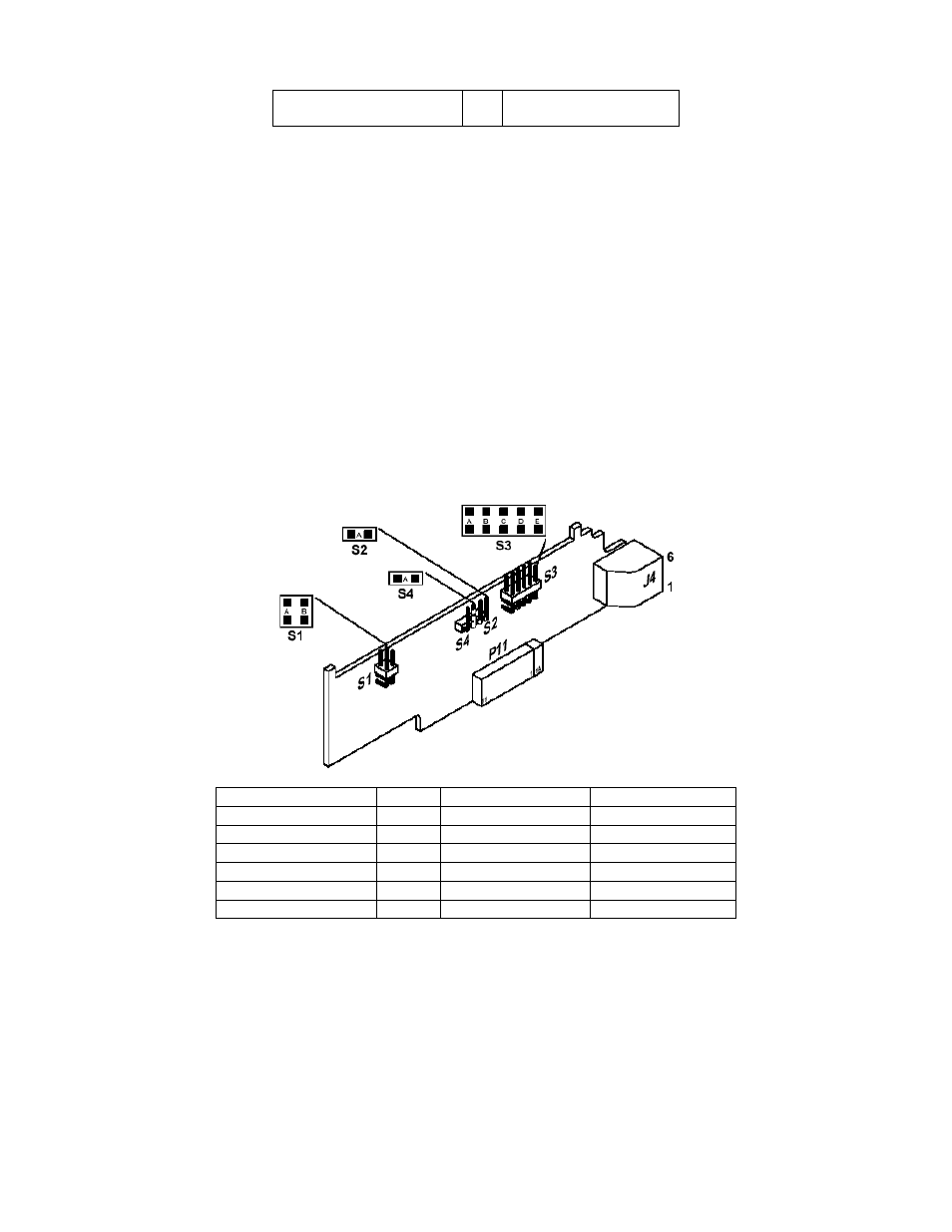
3. The communications board you ordered, plugs into the main board socket (P11 connects into J11 next to the
transformer) with the 6-pin telephone socket. J4 is then protruding out of the rear of the case.
4. Choose baud rate from 300 to 19200. Standard factory setting is 9600.
5. Wide choice of commands and message formats available.
Figure 15-1 gives the board connections and pin designators for RS-232/RS-485.
Meter RJ-12 Pin (J4) RS232 RS485 Half Duplex RS485 Full Duplex
6
5 GND
4 RX
RX-
3 TX
RX-TX- TX-
2 RTS
RX+/TX+ RX+
1
TX+
Figure 15-1. RS-232/RS-485 Option Board and Pin Designations
Figure 15-2 shows board connections and pin designators for older RS-232 and RS-485 option cards.
CF 67
64
M1291/N/0403 11279ML-02 Rev. A