1 features overview, 2 unlocking the features – Cooper Instruments & Systems DFI INFINITY Digital Force Indicator/Controller User Manual
Page 55
10.1 Features Overview
1. Four full-range levels with many menu programmable features.
2. Independent operation or ganged action (including guard-band assignments).
3. Active above or below level, outside or inside band.
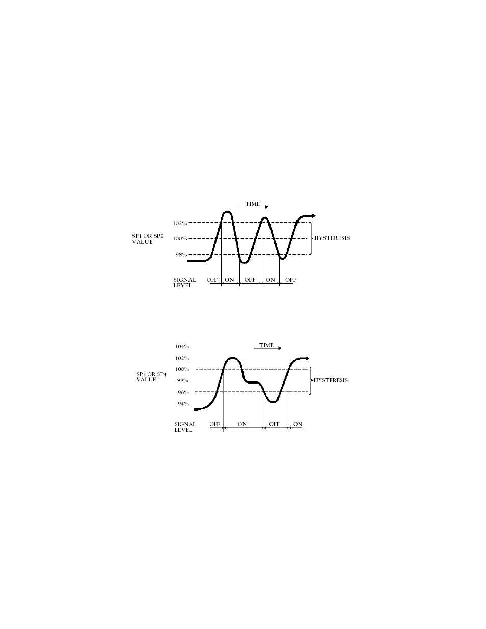
4. SP1 and SP2 have configurable hysteresis, 50% on either side of setpoint.
5. SP3 and SP4 have configurable hysteresis, 100% on inactive side.
6. SP3 and SP4 is configurable for latching action.
7. Setpoint levels can be compared to the unfiltered or filtered input signal measurements.
8. Configurable delays in alarm action.
9. Individual front-panel LED indicators.
10. Four (4) open-collector transistor outputs with clamping diodes, are isolated from signal input.
11. Setpoints can be displayed and reset as desired without interrupting measurements.
Setpoints 1 and 2 have selectable hysteresis, allocated 50% on either side of the setpoint level. A single setpoint
can now generate on/off control signals for an operating region defined by the hysteresis. Refer to Figures 10-1 and
10-2 to understand how hysteresis works:
Figure 10-1. Setpoints 1 & 2 Action (Setpoint at 100 with 4% hysteresis)
These two setpoints have selectable single-sided hysteresis. When used as alarms, the action is immediate (unless
a delay is programmed) going into the alarm zone but turning off is deferred (if latching is not programmed) by the
hysteresis amount.
Figure 10-2. Setpoints 3 & 4 Action (for Low Alarm with Relay on at -100, relay off at –96 with a hysteresis of 4)
You are now able to program the setpoint features (as described in the following sections).
10.2 Unlocking The Features
All setpoint values and features can be set via the front-panel buttons or the optional serial communications boards
(RS-232 or RS-422/485). Control from the front-panel buttons can be locked out by jumpers on S3A and S3C on
the main board or by setting lockout bits “L3C.2”, and “L3C.6” in Lockout configuration “L3 CNF”.
1. Check that main board jumpers S3A and S3C are installed (to permit memory storage of program and data
along with button controls).
NOTE: Jumper S3B should NOT be installed. This jumper is reserved for factory recalibration!
CF 67
50
M1291/N/0403 11279ML-02 Rev. A