3 selecting sp cnf setpoint configuration features, 4 deviation function for alarms – Cooper Instruments & Systems DFI INFINITY Digital Force Indicator/Controller User Manual
Page 56
2. Press the ‘MENU’ button to see “L1 CNF” and then press the ‘MIN’ button to view “L1C.1=0” if “SP 1” is
unlocked. If “L1C.1=1”, change to equal “0” by pressing the ‘MAX’ button.
3. Press the ‘MIN’ button again to advance to “L1C.2” and set equal to “0” to unlock “SP 2”.
4. Repeat for “L1C.3=0” and “L1C.4=0” to access “SP 3” and “SP 4”.
5. Press the ‘MENU’ button to save these choices and advance to “L2 CNF”. Skip over “L2 CNF” by pressing the
‘MENU’ button and advance to “L3 CNF”.
6. Press the ‘MIN’ and ‘MAX’ buttons to set “L3C.2=0”, “L3C.3=0”, “L3C.4=0”, “L3C.5=0”, “L3C.6=0”, “L3C.7=0” to
gain access to the programming for the setpoints. All changes are then saved by pressing the ‘MENU’ button.
10.3 Selecting SP CNF Setpoint Configuration Features
These eight bits select the modes for “SP 1” and “SP 2” (see Section 10.5 for “SP 3” and “SP 4”).
1. Press the ‘MENU‘ button until “SP CNF” is displayed, then press the ‘MIN’ button to sequence through the
selections. Use the ‘MAX’ button to choose alternate choice.
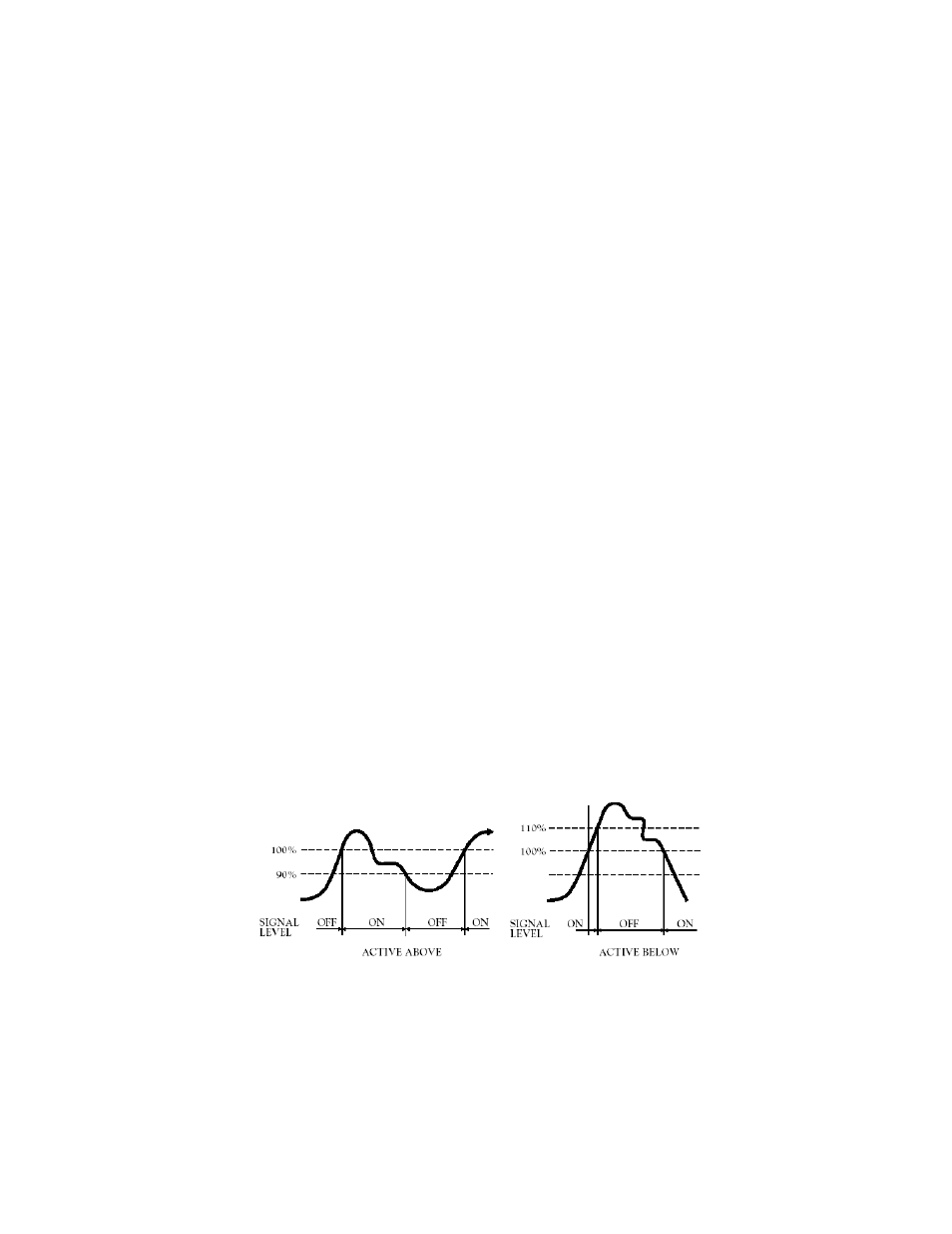
2. “SPC.1=0” makes “SP 1” active ABOVE its level;
“SPC.1=1” sets “SP 1” active BELOW.
3. “SPC.2=0” turns “SP 1” transistor ON when “SP 1” is active.
“SPC.2=1” turns it OFF.
4. “SPC.3=0” compares the “SP 1” level to the UNFILTERED measurements.
“SPC.3=1” compares “SP” to the FILTERED measurements.
5. “SPC.4=0” makes “SP 2” active ABOVE setpoint.
“SPC.4=1” makes “SP 2” active BELOW setpoint.
6. “SPC.5=0” turns “SP 2” transistor ON when “SP 2” is active.
“SPC.5=1” turns it OFF.
7. “SPC.6=0” compares the “SP 2” level to the UNFILTERED measurements.
“SPC.6=1” compares “SP” to the FILTERED measurements.
8. “SPC.7=0” Enables both setpoints 1 and 2.
“SPC.7=1” Disables both setpoints 1 and 2.
9. “SPC.8=0” ENABLES the two front-panel LED indicators for setpoints 1 and 2 when you have chosen “SPC.7=0”.
“SPC.8=1” DISABLES the two front-panel LED indicators for setpoints 1 and 2. (use with caution;
recommended only when other external over-range indicators are present).
10. Press the ‘MENU’ button to store your selections and advance to “AL CNF” (Alarm Configuration).
10.4 Deviation Function For Alarms
Deviation functions apply to Alarms 1 and 2 (Setpoints 3 and 4) and act as buffer zones to control setpoint action.
The Alarm 1 deviation is the sum of the Alarm 1 value plus the Setpoint 1 value; the Alarm 2 deviation is the Alarm
2 value plus the Setpoint 2 value. The four types of deviation functions are Process (no deviation), High, Low, and
Deadband. The following illustrate the ways in which the deviation function alters the alarm response.
Figure 10-3. Process Deviation
CF 67
51
M1291/N/0403 11279ML-02 Rev. A