0 jumper positions, 1 introduction, 3 s2 jumper positions for input ranges – Cooper Instruments & Systems DFI INFINITY Digital Force Indicator/Controller User Manual
Page 20
The meter display should light, and pass through “RESET 2” to run or display mode. If the meter flashes an
overscale or overload message, press the ‘MENU’ button to advance to the configuration mode. Do not be
concerned about overloads (the +S input can stand 120 V continuously and current inputs can handle ten times
rated current).
6.0 JUMPER POSITIONS
6.1 Introduction
This section is for the configuration and setup of your jumper positions for readrate, unipolar or bipolar signal input,
sensor input signal jumpers, sensor excitation jumpers, pushbutton lockouts and lockout of lockout configuration
menus.
6.2 S1 Jumper Positions For Readrate And Unipolar Or Bipolar Input(S)
The typical readrate for your meter is 3/per second. This requires that no jumper has been installed in the S1A
position and Input Configuration (“IN CNF”) bit “INP.2” has been set to equal “0”. Your meter is capable of a fast
readrate of 13/per second. This requires that you install a jumper in the S1A position and the Input Configuration
(“IN CNF”) bit “INP.2” has been set to equal “1”. Refer to Figure 6-1 for the location of the S1 jumpers.
The typical setting for your meter is unipolar. For unipolar input, no jumper is installed in the S2B position and Input
Configuration (“IN CNF”) bit “INP.3” must be set to equal “0”. For bipolar inputs, install a jumper in S1B and set
Input Configuration (“IN CNF”) bit “INP.3” to equal “1”.
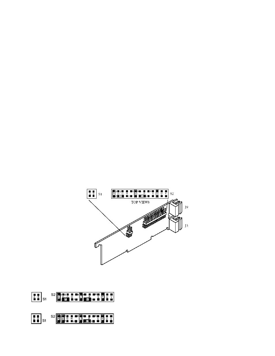
6.3 S2 Jumper Positions For Input Ranges
The following are the input signal jumper positions required to be installed in the “S2” position on your meter for the
current or voltage input ranges you require. These jumper positions include those that are required for sensor
excitation. Jumpers S2-N & S2-T are for either 1.5 to 11 Vdc or 24 Vdc sensor excitation. To select desired
excitation see Section 6.4. Refer to Figure 6-1 for the location of the S2 jumpers.
Figure 6-1. S1 and S2 Jumper Locations on Signal Input Board
BRIDGE – UNIPOLAR
Jumpers for 0 to 100 mV range: (meter supplied excitation)
Jumpers for 0 to 1 V range: (meter supplied excitation)
CF 67
15
M1291/N/0403 11279ML-02 Rev. A