5 board installation: entering the trim data – Cooper Instruments & Systems DFI INFINITY Digital Force Indicator/Controller User Manual
Page 62
3. Store this value by pressing the ‘MENU’ button and then advance to “READ2”. Use the ‘MIN’ and ‘MAX’ buttons
to enter a large display value, for example, “123.456”, for the display that you want the analog output at full
scale.
4. Store this value by pressing the ‘MENU’ button and then advance to “OUTPT2”. Use the ‘MIN’ and ‘MAX’
buttons to enter the desired output for the display value in step 3. For example, enter “20.0000” for calibrated
current or “10.0000” for calibrated voltage.
5. Press the ‘MENU’ button to store. Press the ‘RESET’ button two times to return to run mode and check
calibration points, unless your analog output board is newly installed; in this case, follow Section 12.5.
12.5 Board Installation: Entering The Trim Data
To precisely calibrate your analog output board with your meter, each analog output board has been supplied with
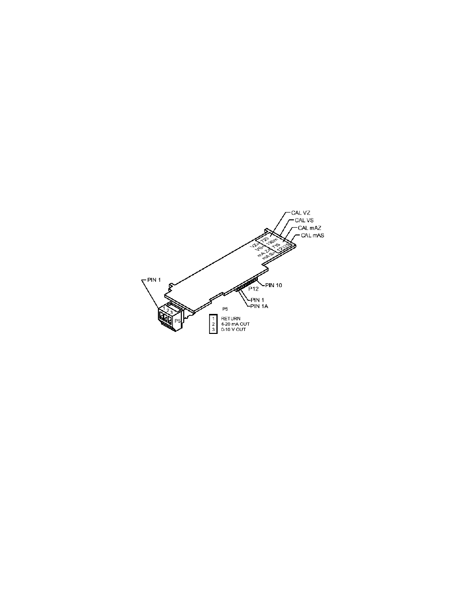
voltage and current zero trim values printed on the board. “CAL VZ” is for the voltage output and “CALmAZ” is for
the current output.
Similarly, the fine trim for output gain is “CAL VS” for the voltage output and “CALmAS” for the current output.
These 4 data points are obtained from the factory calibration of each analog output board and are inscribed on the
top edge of each board, as shown in Figure 12-1.
Figure 12-1. Analog Option Board and Connection Diagram at P5.
If you are installing an analog output board, follow this “one time only” procedure:
1. Write down the four (4) numbers inscribed on the top edge of your analog output board below:
CAL VZ=
CAL VS=
CALmAZ=
CALmAS=
2. “Reveal the main board” and install the analog output board using the procedures outlined in Section 5.2.
3. Attach connector wires, insert connectors, and apply power to the meter as described in Section 5.3.
4. If not already unlocked, press the ‘MENU’ button until “L4 CNF” is displayed and press the ‘MIN’ button six
times. Now press the ‘MAX’ button to set “L4C.6=0”.
5. Press the ‘MENU’ button to store and advance to “CAL VZ”. Use the ‘MIN’ and ‘MAX’ buttons to enter the
value (recorded from the edge of the board).
6. Press the ‘MENU’ button to store and advance to “CAL VS”. Use the ‘MIN’ and ‘MAX’ buttons to enter the
value.
7. Repeat for “CALmAZ”.
8. Repeat for “CALmAS”.
9. Press the ‘MENU’ button to store your entries and then you will see “C.JUN.OF”. Press the ‘RESET’ button two
times and you will see “RESET2”, followed by “RUN”. Verify your calibration points for the analog output.
10. Jumper S1-A does not need to be installed, but located in a storage position.
CF 67
57
M1291/N/0403 11279ML-02 Rev. A