5 selecting al cnf alarm configuration features – Cooper Instruments & Systems DFI INFINITY Digital Force Indicator/Controller User Manual
Page 57
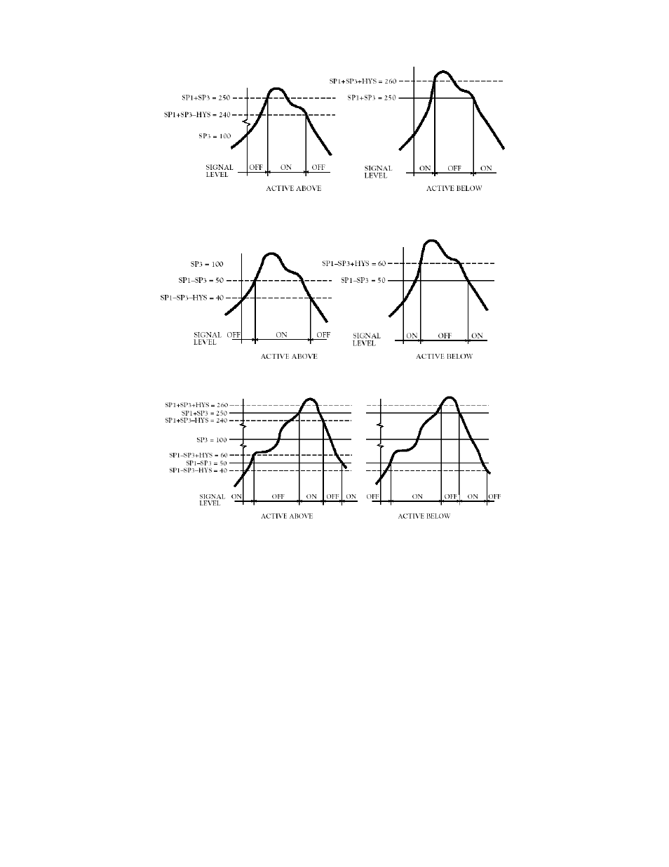
Figure 10-4. High Deviation for both Active Above and Active Below
Figure 10-5. Low Deviation for both Active Above and Active Below
Figure 10-6. Band Deviation for both Active Above and Active Below
10.5 Selecting AL CNF Alarm Configuration Features
These bits offer the same selections for “SP 3” and “SP 4” as “SP CNF” did for “SP 1” and “SP 2”, except for the
last bit, which controls “SP 3” and “SP 4” LATCH reset.
1.“ALC.1=0” makes Alarm 1 (Setpoint 3) active above the Setpoint value.
“ALC.1=1” makes Alarm 1 (Setpoint 3) active below the Setpoint value.
When Alarm 1 (Setpoint 3) is assigned to place a band about the Setpoint 1 level (by setting “ALF.1=3”, described
in Section 10.6), “ALC.1=0” makes Alarm 1 (Setpoint 3) active ABOVE and BELOW the band (OUTSIDE the band),
with the chosen hysteresis for Alarm 1 (Setpoint 3) now inside the band. If “ALC.1=1”, Alarm 1 (Setpoint 3) is active
INSIDE the band, with the chosen hysteresis for Alarm 1 (Setpoint 3) now outside the band.
Figure 10-7 Illustrates the Alarm configuration for hysteresis.
CF 67
52
M1291/N/0403 11279ML-02 Rev. A