6 selecting al fnc alarm function features – Cooper Instruments & Systems DFI INFINITY Digital Force Indicator/Controller User Manual
Page 58
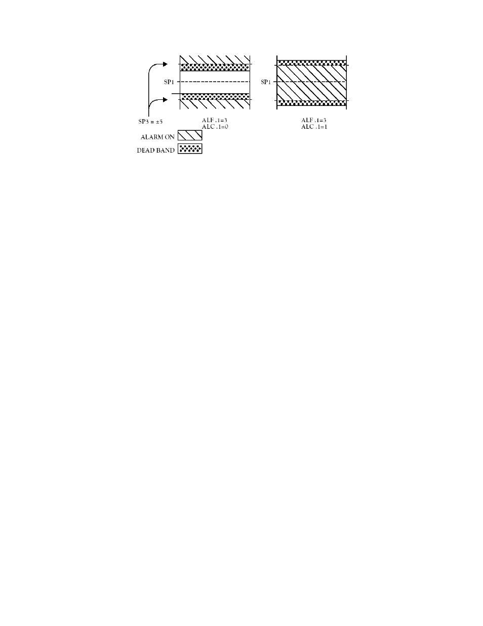
Figure 10-7. AL CNF Hysteresis
2.“ALC.2=0” turns the Alarm 1 (Setpoint 3) open-collector output ON when Setpoint 3 is active.
“ALC.2=1” turns it OFF.
3. “ALC.3=0” compares the Alarm 1 (Setpoint 3) level to the UNFILTERED measurements.
“ALC.3=1” compares the Alarm 1 (Setpoint 3) level to the FILTERED measurements.
4.“ALC.4=0” makes Alarm 2 (Setpoint 4) active ABOVE the Setpoint value.
“ALC.4=1” makes Alarm 2 (Setpoint 4) active BELOW the Setpoint value.
When Alarm 2 (Setpoint 4) is assigned to place a band about the Setpoint 4 level (by setting “ALF.1=3”, described
in Section 10.6), “ALC.4=0” makes Alarm 2 (Setpoint 4) active ABOVE and BELOW the band (OUTSIDE the band),
with the chosen hysteresis for Alarm 2 (Setpoint 4) now inside the band. If ALC.4=1”, Alarm 2 (Setpoint 4) is active
INSIDE the band, with the chosen hysteresis for Alarm 2 (Setpoint 4) now outside the band.
5.“ALC.5=0” turns the Alarm 2 (Setpoint 4) open-collector output ON when Setpoint 1 is active.
“ALC.5=1” turns it OFF.
6. “ALC.6=0” compares the Alarm 2 (Setpoint 4) level to the UNFILTERED measurements.
“ALC.6=1” compares the Alarm 2 (Setpoint 4) level to the FILTERED measurements.
7.“ALC.7=0” ENABLES both Alarms 1 and 2 (Setpoints 3 and 4) action and LEDs.
“ALC.7=1” DISABLES both Alarms 1 and 2 (Setpoints 3 and 4) action and LEDs.
8.“ALC.8=0” DISABLES Alarm reset at the P2-11 connector.
“ALC.8=1” ENABLES Alarm reset at the P2-11 connector.
Press the ‘MENU’ button to store any changes and advance to “AL FNC” (Alarm Function).
10.6 Selecting AL FNC Alarm Function Features
This byte allows you to select independent or ganged operation for “SP 3” and “SP 4”, and whether or not they
should latch once triggered.
1.“ALF.1=0” makes Alarm 1 (Setpoint 3) INDEPENDENT, with a level equal to the value inserted for Setpoint 3.
“ALF.1=1” assigns Setpoint 3 (“SP 3”) to Setpoint 1 (“SP 1”), placing it ABOVE Setpoint 1 (“SP 1”) by the amount
entered for Setpoint 3 (“SP 3”).
“ALF.1=2” places “SP 3” BELOW “SP 1” by the amount entered for “SP 3”.
“ALF.1=3” places “SP 3” ON BOTH SIDES OF “SP 1” by the amount entered for “SP 3”.
2.“ALF.2=0” makes Alarm 1 (Setpoint 3) a NON-LATCHING Alarm.
“ALF.2=1” makes Alarm 1 (Setpoint 3) LATCHING. This means that once Alarm 1 (Setpoint 3) is triggered it will
remain active until it is reset by pressing the ‘RESET’ button one time or by grounding P2-11 when configuration bit
“ALC.8=1” is set.Reset can also be accomplished via the optional RS-232 or RS-485 serial communication board.
CF 67
53
M1291/N/0403 11279ML-02 Rev. A