Cooper Instruments & Systems DFI INFINITY Digital Force Indicator/Controller User Manual
Page 19
2. You have configured all jumpers – those on the main board as well as those on any optional boards. See
Section 5.2.2 for main board jumper configuration and the appropriate sections for optional board jumper
configuration.
3. You have installed all optional boards and inserted the main board assembly back into the case. See Section
5.2.3.
4. You have wired P1, the AC power connector, and P2 the input output control connector; connectors are not
installed in the meter, but are ready to be installed. See Section 7.
5. You have wired all connectors for optional boards; connectors are not connected to the meter, but are ready to
be installed.
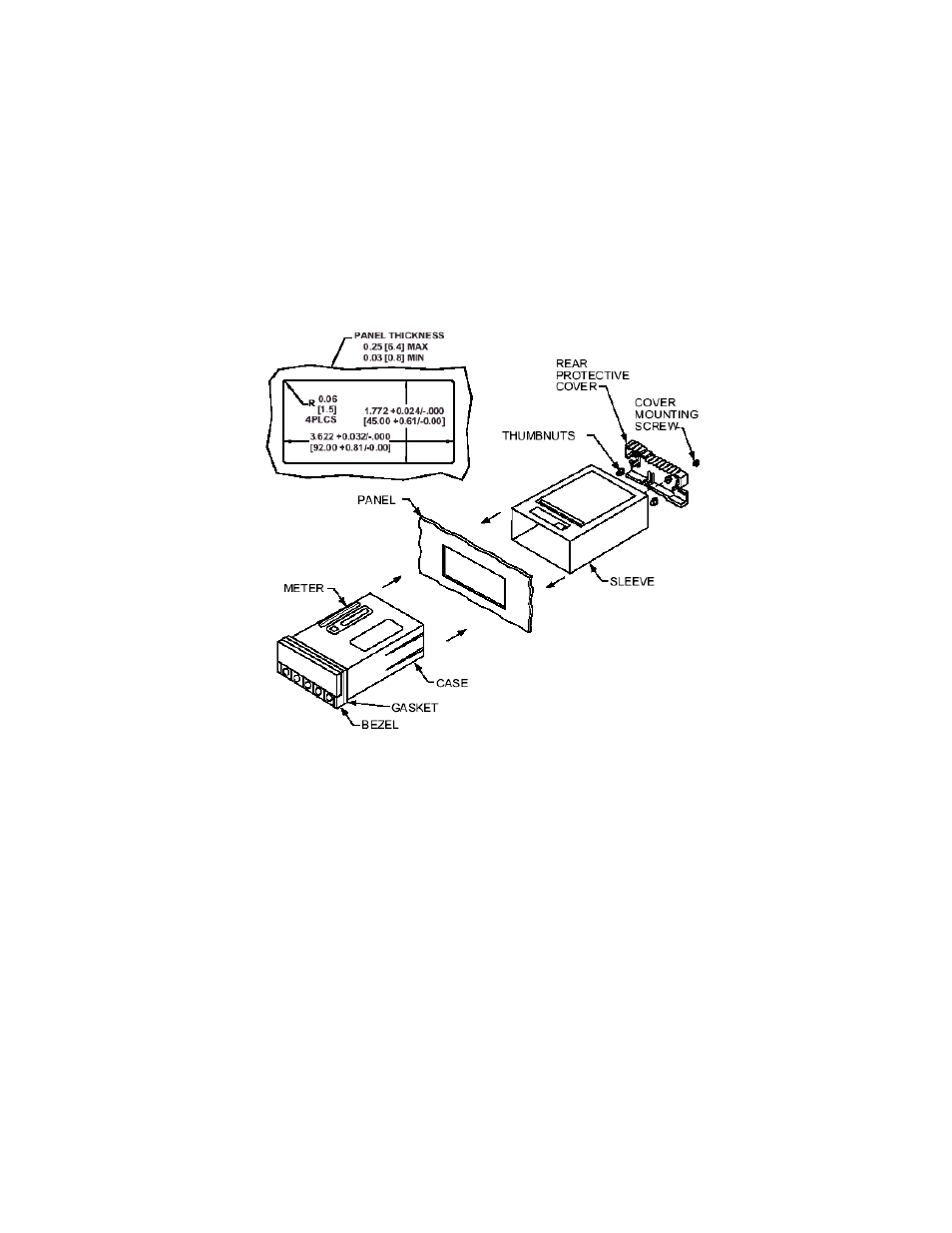
If all of these steps are done, use Figure 5-14 as a guide:
CAUTION: Connectors with the wiring connections will be installed after mounting the unit.
Figure 5-14. Panel Mounting Assembly
6. Punch or cut a hole in the panel using the panel cutout dimensions in Figure 5-14. Remove burrs and paint the
panel as required
7. Insert the panel-mount gasket around the rear of the case and slide it forward to the bezel (if it’s not already in
place).
8. Working from the front of the panel, insert the case assembly, rear end first, all the way into the panel cutout
such that the gasket firmly backs the panel surface.
9. Working from the rear of the panel, slide the sleeve forward over the case and up to the panel surface. The
panel should now be sandwiched between the bezel-backed gasket in front and the sleeve in back.
10. Replace the thumbnuts that secure the sleeve tabs to the case.
WARNING: Do not “turn-on” the ac power and input signals until all connections are connected to the meter.
11. Set P1, the AC power connector, aside and connect or reconnect all other connectors to the back of the meter
using Figures 4-3 and 4-4 in Section 4.2 as guides. Connect P1 last.
NOTE: The P1 connector is “keyed”; it is shaped in such a way that it fits only the J1 male pins.
Your meter is now ready for operation and you can turn-on the power.
CF 67
14
M1291/N/0403 11279ML-02 Rev. A