Harrow setup, Harrow height setup, Harrow tine setup – Great Plains V-300F Operator Manual User Manual
Page 33: Harrow height setup harrow tine setup
Great Plains Manufacturing, Inc.
Setup
29
11/15/2007
148-057M-A
Harrow Setup
Before first use, check the height and the tine angle of
the harrow.
Harrow Height Setup
Lower the drill. If the harrow is locked up, remove the
pins
securing the harrow lockup
to the chains.
Lay the lockup down on the harrow arm
2.
Raise the drill and insert lift locks.
3.
Measure the distance from the bottom of the press
wheels to the ground.
4.
Lift the harrow until the lowest tine ends are at this
same height.
5.
Relocate the clevis
on each chain until the harrow
is supported at this height.
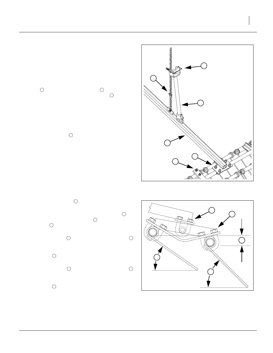
Harrow Tine Setup
The setup shown in Figure 30 has proven successful in
no-till and minimum till conditions. Your field conditions
may require adjustment due to soil type, residue type
and amount, and moisture levels.
To set the tines to factory-recommended values:
Refer to Figure 29 and Figure 30
1.
Lower the drill to field position and pull forward.
2.
Loosen the eight nuts
on U-bolts securing the arm
to the tine assembly.
3.
Rotate the assembly until the front frame tube
is
higher than the rear frame tube
by:
elevation
: 2.5cm or 1in.
Tighten the nuts.
4.
Loosen the 4 nuts
securing the front frame tube
to the tube support.
5.
Rotate the front tube to:
tine angle
: 35
°
Tighten the nuts.
6.
Loosen the 4 nuts
securing the rear frame tube
to the tube support.
7.
Rotate the rear tube to:
tine angle
: 45
°
Tighten the nuts.
8.
Re-check the height when lifted.
Figure 29
Harrow Chain Setup
27261
1
3
2
6
5
4
3
Figure 30
Harrow Tine Setup
14612
7
8
9
F
R
F
R
F
R