25 series row-unit side wheels – Great Plains YP1625 Operator Manual User Manual
Page 91
Great Plains Manufacturing, Inc.
Maintenance and Lubrication
87
03/12/2012
401-226M-A
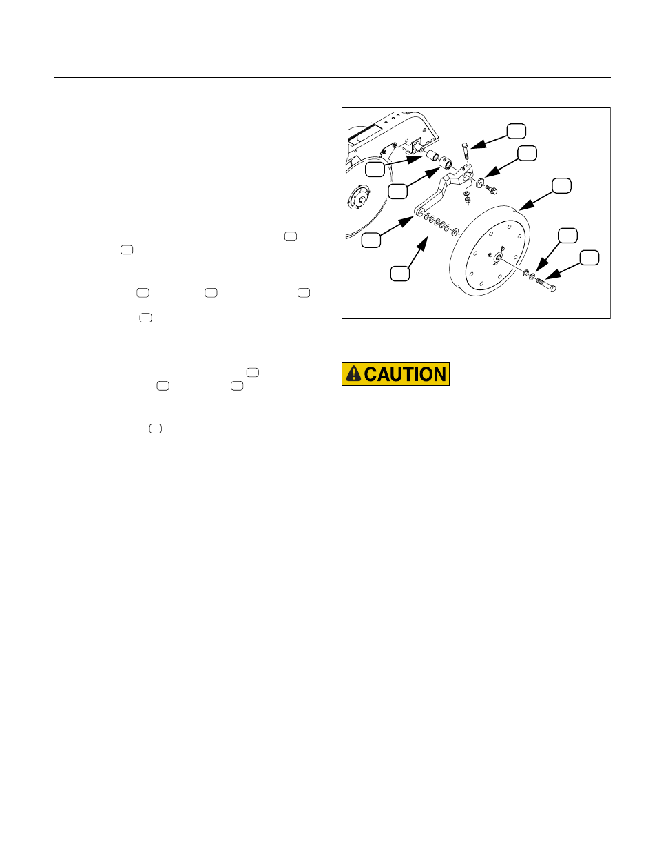
25 Series Row-Unit Side Wheels
Figure 126
1.
Lift opener side wheel off the ground. Move tire in
and out to check for end play. Check for roughness in
bearing by rotating wheel. If bearings are rough,
inspect and replace if necessary.
2.
The side wheels are preset at the factory. However,
because of normal wear it may become necessary to
make adjustments so the wheel remains close to the
disk. To prevent plugging, loosen clamp bolt
and
slide arm
inward to take up gap between side
wheel and disk blade. If more adjustment is needed,
continue at step 3.
3.
Remove bolt
and wheel
. Remove shims
from the inside of wheel and place them on the out-
side of wheel
. Always place removed shims from
the inside to the outside. When installed, wheel
should turn freely and not hit the arm at the curve.
Do not add any more shims than necessary.
4.
Disassemble side gauge wheel arm
from unit.
Remove bushing
from sleeve
and check for
wear. If necessary, replace bushing.
5.
When reinstalling side gauge wheels, align tab on
hex adjustment
with notch in bushing. Replace
bolt and tighten.
6.
Adjust side gauge wheels. See “Side Gauge Wheel
Adjustments” on page 61.
FigureSpacer:
Sharp Object Risk:
Disk edges are sharp. Be careful when working in this area.
Figure 126
Adjusting Gauge Wheel Spacing
21894
14
11
17
16
10
18
13
15
12
{
10
11
12
13
14
15
11
16
17
18