Marker setup, Marker extension – Great Plains YP1625 Operator Manual User Manual
Page 133
Great Plains Manufacturing, Inc.
Appendix B - Initial Setup
129
03/12/2012
401-226M-A
Marker Setup
Although markers are factory- or dealer-installed, they
are not precisely adjusted for your planter configuration.
Prior to first use, set the following:
• marker speed (page 49), and;
• marker extension (below).
You may also want to set/check:
• marker disc angle (page 49).
Marker Extension
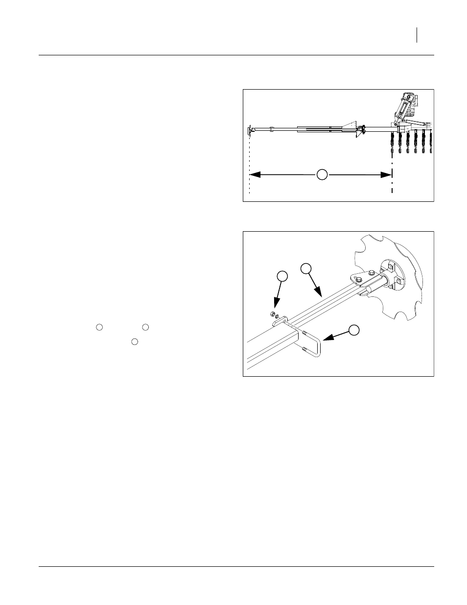
Refer to Figure 147
Marker Extension is the distance from the mark in the
ground to the centerline (or furrow) of the end row unit
(whether that row is in use or not).
The tables on page 128 provide suggested initial values
for various standard and altered configurations. When
operating with rows locked up, measure to the outside
row whether in use or not. Extension values may be dif-
ferent for left and right side, and may be different for
opposing passes (each pass in the opposite direction)
and concentric passes (each pass in the same direction).
The table only includes data for opposing passes.
Refer to Figure 148
To adjust marker extension:
1.
Loosen nuts
on U-bolts
.
2.
Move marker disk tube
in or out to get the proper
adjustment.
3.
To measure for marker width adjustment:
4.
Lower planter in the field and drive forward a few
feet.
5.
Measure from the centerline/furrow of the outside
active row to the mark in the ground made by marker
disk.
When correctly adjusted, there is a gap of one row space
between passes, as measure between center-lines of
outside active rows for single-row, or between center-
lines outside active twin row pairs.
End of “Appendix B - Initial Setup”.
FigureSpacer:
Figure 147
Marker Extension
27451
1
FigureSpacer:
Figure 148
Adjusting Marker Extension
18878
5
3
4
4
3
5