Electric clutch operation, Electric clutch lockup – Great Plains YP1625 Operator Manual User Manual
Page 44
40
YP1225 and YP1625
Great Plains Manufacturing, Inc.
401-226M-A
03/12/2012
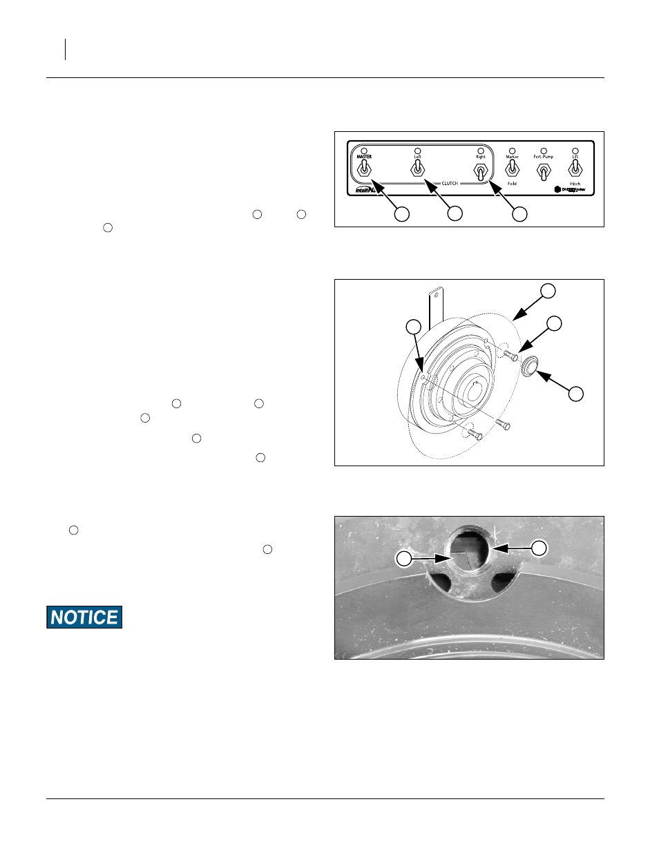
Electric Clutch Operation
Refer to Figure 49, which depicts the left planter side on and
the right side shut off.
Electric clutches allow for turning planting off while the
planter is lowered. A clutch for each drive shaft allows for
independent control of each side of the planter. The
clutches are controlled via the CFM “CLUTCH” switches.
For regular field operation, turn “MASTER”
and “Right”
clutch switches to the “ON” position. This
activates the magnet on each clutch and allow clutch
shafts to rotate.
To shut off planting on one or both sides to accommo-
date point row while planter is lowered, switch either to
“OFF” position. Turning the MASTER switch off disen-
gages both sides. If the planter has hydraulic meter
drive, MASTER off also shuts down the drive motor.
Electric Clutch Lockup
Refer to Figure 50
In case of electric clutch failure, electric clutches can be
bolted together.
1.
Remove rubber plugs
access to bolts
.
2.
Align cutouts at bolt holes
.
3.
Insert M8-1.25x14mm long metric bolts
.
Note: Use only 14mm length bolts as provided or ma-
chine damage will occur. Longer bolts will damage
the clutch. Shorter bolts may not effect a lock-up.
If you observe half the hole obstructed by a metal
disc
, you are not at a cutout.
If the entire hole is obstructed by a metal disc
, you are
not at a cutout.
When at a cutout, the bolt will screw in with minimal
resistance until the bolt head reaches the clutch face.
Clutch Slippage Risk:
When lubricating the planter, do not allow lubricant to enter
the clutch, or clutch slippage will result.
FigureSpacer:
FigureSpacer:
Figure 49
CFM: Point Row
28490
1
2
3
1
2
FigureSpacer:
Figure 50
Electric Clutch Lockup
29329
4
3
2
1
2
3
4
3
FigureSpacer:
Figure 51
Clutch Plate Nearly at Cutout
26168
5
4
5
5