Transmig 250i installation/setup – Tweco 250i Transmig Inverter User Manual
Page 46
TRANSMIG 250i
INSTALLATION/SETUP
INSTALLATION/SETUP 3-28
Manual 0-5187
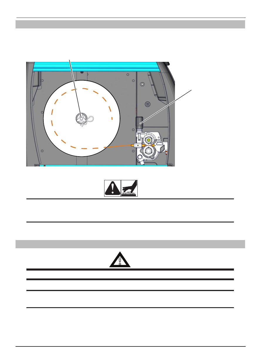
3.21 Wire Reel Brake
The wire reel hub incorporates a friction brake which is adjusted during manufacture for optimum braking. If it is
considered necessary, adjustment can be made by turning the tri-lobe nut inside the open end of the wire reel hub.
Clockwise rotation will tighten the brake. (Refer to Figure 3-25).
Pressure Adjustment
Knob
Wheel Brake adjusting tri-lobe nut
Art # A-10032
Figure 3-25: Wire Installed
CAUTION
Excessive tension on the brake will cause rapid wear of mechanical wire feed parts, over heating of electrical
componentry and possibly an increased incidence of wire Burnback into the contact tip.
NOTE
Correct adjustment will result in the wire reel circumference continuing no further than 20mm after release
of the MIG Torch trigger switch. The wire should be slack without becoming dislodged from the reel.
3.22 Shielding Gas Regulator Operating Instructions
!
WARNING
This equipment is designed for use with welding grade (Inert) shielding gases only.
NOTE
Shielding Gas Regulator not included in the Transmig 250i (Asia Version) Plant Part No W1003250M.
NOTE
Shielding Gas is not required if the unit is used with self shielded FCAW (flux cored arc welding) wires