Installation/setup transmig 250i, 20 input and output wire guide installation – Tweco 250i Transmig Inverter User Manual
Page 45
INSTALLATION/SETUP
TRANSMIG 250i
Manual 0-5187
3-27 INSTALLATION/SETUP
3.20 Input And Output Wire Guide Installation
NOTE
0.9mm / 1.2mm feed rolls and guides are installed from the factory. Other sizes need to be purchased
separately.
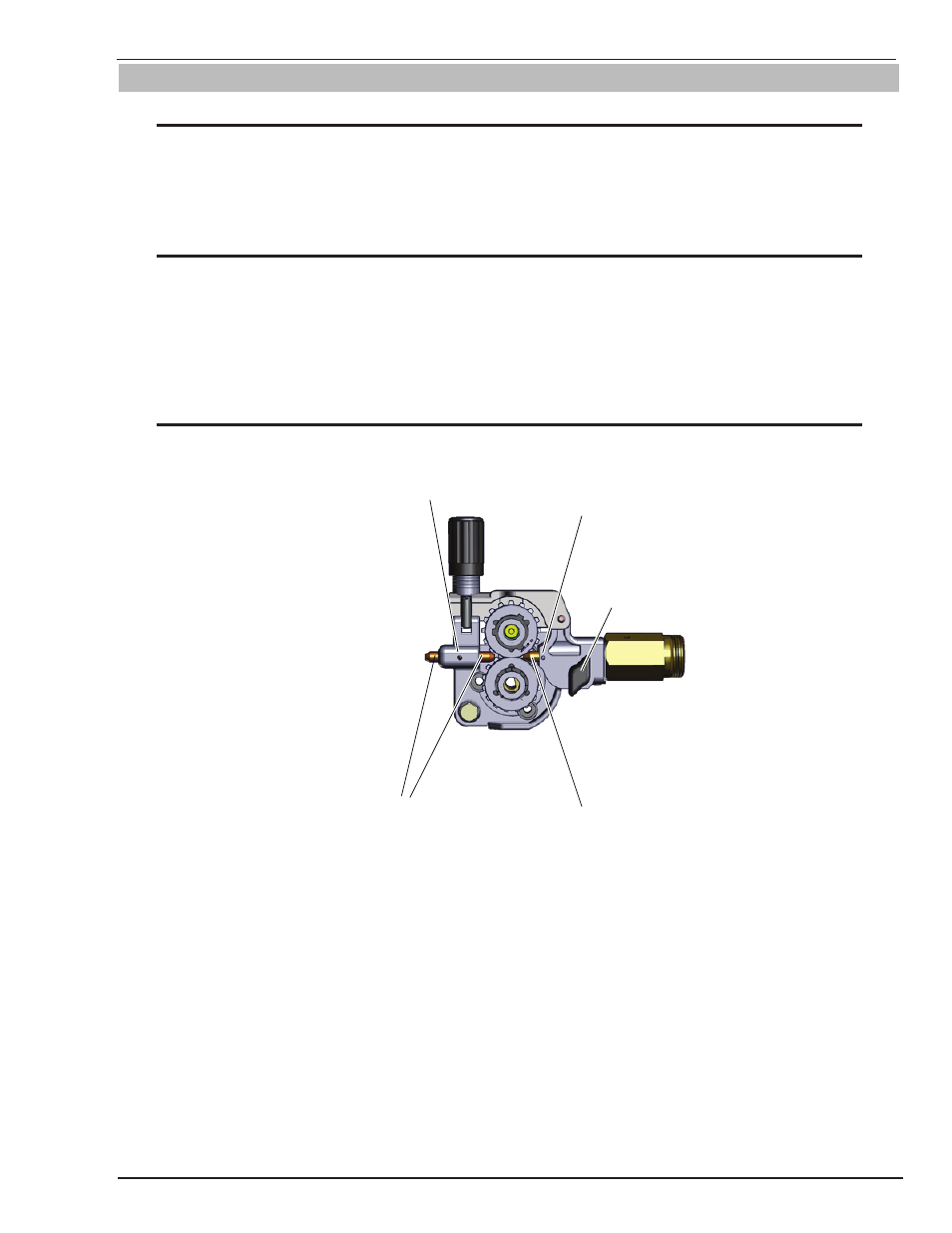
Input Wire Guide - Install (the shorter one) by loosening the input guide lockscrew and inserting the guide into the hole
in the feedhead assembly. Adjust the guide so that it is clear of the feed rolls and tighten the input guide lockscrew.
NOTE
Before tightening the input and output guide lockscrews, install the drive roll to help in the alignment of
the wire guides.
Output Wire Guide - With the MIG Torch removed, loosen the adapter nut. This will aid with alignment. Install the
output wire guide (the longer one) by inserting the conical end part way into the Euro Adapter from the front of the
machine. Now install the MIG Torch pressing the output guide further in until the tip of the guide is as close to the
feed rolls as practical. Secure the MIG Torch. Tighten the adapter lock nut then tighten the output guide lockscrew.
NOTE
Gently strike the electrode on the work piece to generate a welding arc, and slowly move along the work
piece while holding a consistent arc length above base metal.
Art # A-10346
Input Guide Lockscrew
Output Guide Lockscrew
Input Wire Guide
Output Wire Guide
MIG Torch
Adapter Lock
Nut
Figure 3-24: Wire Guide Installation