Transmig 250i installation/setup – Tweco 250i Transmig Inverter User Manual
Page 38
TRANSMIG 250i
INSTALLATION/SETUP
INSTALLATION/SETUP 3-20
Manual 0-5187
3. Temporarily remove the top center screw in the 250i case. Attach the top tray using four screws provided ensur-
ing the tab on the front of the tray captures the hand hold on the front of the 250i power source. Re-install the
screw through the hole in the centre of the top tray into the top of the 250i case. Ensure that all fixing screws
are in place and tightened.
4. Place rubber mat on the top tray and then place the 2RT Wire Feeder on that.
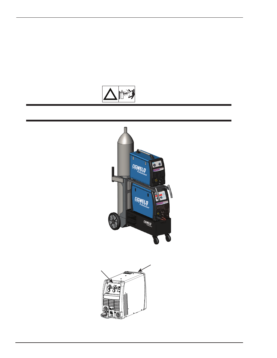
5. Position a gas cylinder on the rear tray of the Trolley and lock securely to the Trolley cylinder bracket with the
chain provided. If this arrangement is not used then ensure that the gas cylinder is secured to a building pillar,
wall bracket or otherwise securely fixed in an upright position.
6. Attach Gas Regulator and hose per instructions found in sub Section 3-22.
!
WARNING
Secure the welding grade shielding gas cylinder in an upright position by chaining it to a suitable stationary
support to prevent falling or tipping.
Art # A-10327
Secure the welding grade
shielding gas cylinder in
an upright position by
chaining it to a suitable
stationary support to
prevent falling or tipping.
Figure 3-15: Welding Trolley and Welding Equipment
Front Hand Grip
Art # A-10407
Rear Hand Grip
Figure 3-16: Location of Hand Grips