Installation/setup transmig 250i – Tweco 250i Transmig Inverter User Manual
Page 23
INSTALLATION/SETUP
TRANSMIG 250i
Manual 0-5187
3-5 INSTALLATION/SETUP
+
-
11
12
13
14
15
Art # A-10319
16
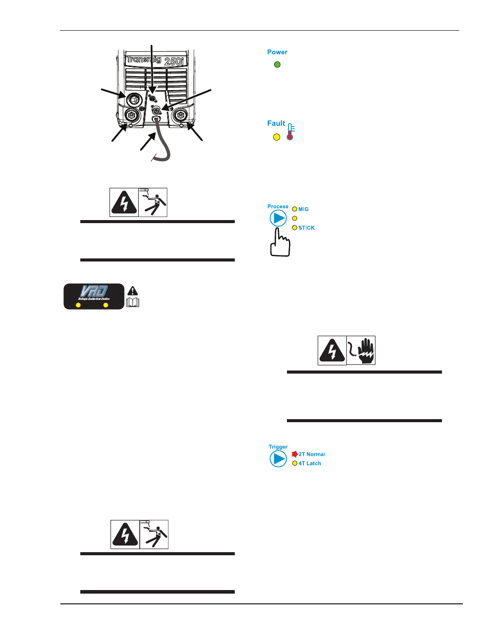
Figure 3-2: Transmig Front Connections
WARNING
DO NOT TOUCH the electrode wire while it is
being fed through the system. The electrode
wire will be at welding voltage potential.
1. VRD Indicator
ON
OFF
A VRD (voltage reduction device) is designed to reduce
electric shock hazards present on the output of welding
power source when operating in STICK mode. Note that
the presence of VRD should not be used as a substitute
for the use of appropriate safety practices as indicated in
section one of this manual.
Both the green and red indicator lights only operate in
STICK mode.
The green VRD ON light illuminates (red light is OFF)
when the VRD is active. Under this condition the open
circuit voltage of the unit is limited to below 35V DC, thus
reducing the potential of serious electric shock (such as
when changing electrodes).
The red VRD OFF light illuminates (green light is OFF)
when the VRD is inactive. Under this condition the output
voltage of the unit will be at welding potential which in
some cases may exceed 35V DC.
WARNING
When the red VRD indicator is on and welding
is being performed, the presence of dangerous
voltage may be present at the electrode.
2. Power Indicator
The green power indicator will be illuminated when the
welder is turned ON and indicates the presence of power.
3. Fault Indicator
The yellow fault indicator will be illuminated when any
of the faults are detected. ALL Faults will illuminate the
indicator
4. Weld Process Selection Button
LIFT TIG
Press and release this button to change the selected weld
process mode from MIG to LIFT TIG to STICK. The weld
process will change to the next process in the sequence
each time the button is pressed and released. The red
indicators next to the button will illuminate to identify MIG
or LIFT TIG or STICK process mode.
.
WARNING
When the Power light is lit, the machine is
connected to the Mains supply voltage and
the internal electrical components are at Mains
voltage potential.
5. 2T - 4T Trigger Latch Button
Press and release the button to change the selected op-
erating mode of the trigger. The selected mode can be
either “2T” (unlatched) or “4T” (latched) operation. The
red indicator next to the button will illuminate to identify
which mode is selected (2T or 4T). In the 4T mode once
the weld has been started you can release the trigger and
continue welding until the trigger is activated again or the
welding arc is broken to stop the welding arc.