Transmig 250i installation/setup – Tweco 250i Transmig Inverter User Manual
Page 24
TRANSMIG 250i
INSTALLATION/SETUP
INSTALLATION/SETUP 3-6
Manual 0-5187
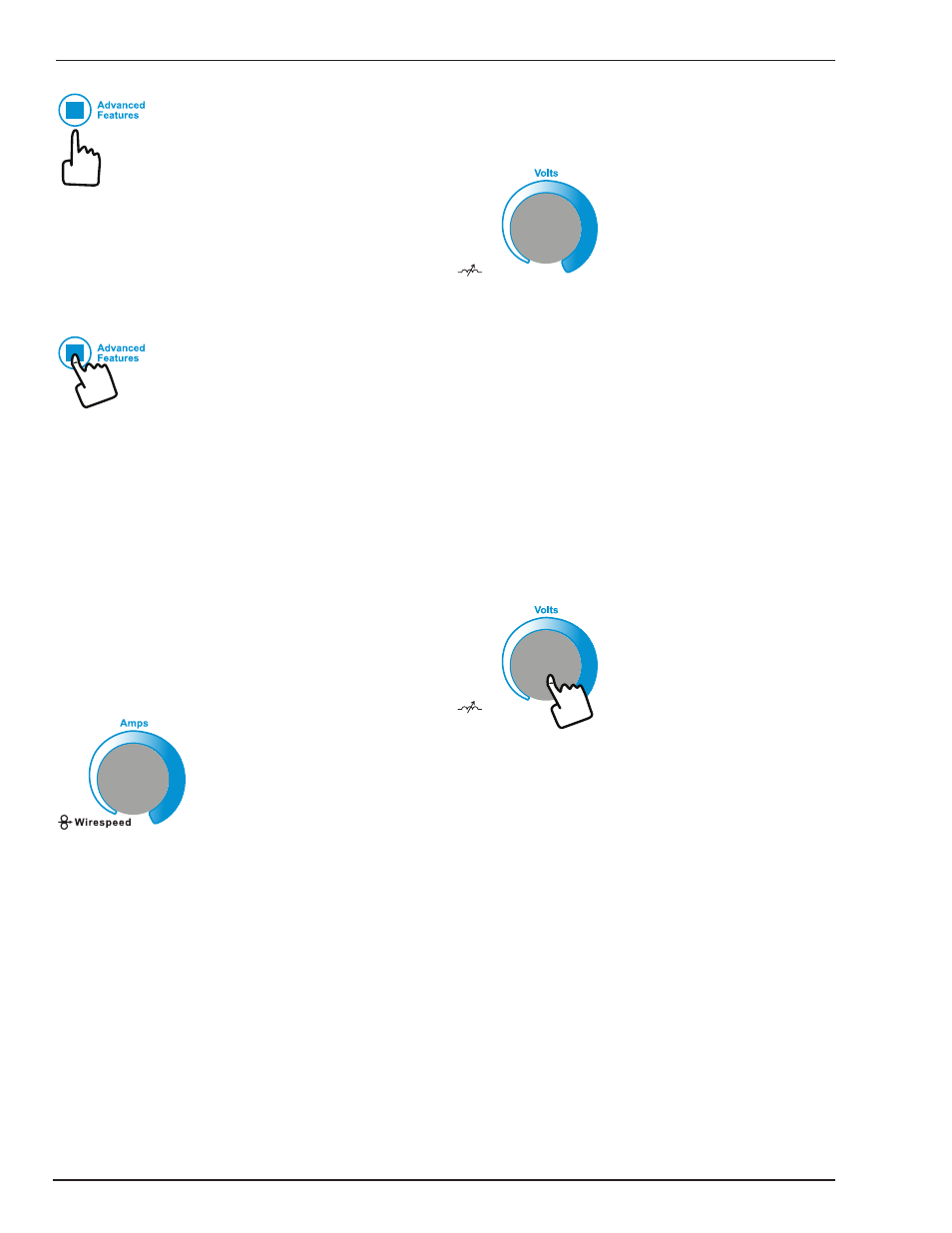
6. Advanced Features Button
Press and release the Advanced Features button to enter
or exit from the advanced programming mode. To exit,
simply press and release the button again. Any changes
made are saved. The advanced programming menu items
are described in detail for each welding mode in Section
3.07.
Gas Purge.
In addition, the Advanced Features Button is used to initi-
ate a 30 second gas line purge function to fill the gas line
with the shielding gas from the connected gas cylinder.
To start the gas purge function, simply press and hold the
button for approximately two (2) seconds. Once the Gas
purge function has started, a countdown timer will show
in the left alpha-numeric display indicating the number
of seconds remaining before the purge will be automati-
cally terminated. You can stop the Gas purge any time
during the 30 seconds by quickly pressing and releasing
the button again.
7. Left Knob: Amperage Control (Wirespeed)
Left Knob
The amperage control knob adjusts the amount of welding
current delivered by the power source. In STICK and LIFT
TIG modes, the amperage control knob directly adjusts the
power inverter to deliver the desired level of output cur-
rent. In MIG mode, the amperage knob adjusts the speed
of the wire feed motor (which in turn adjusts the output
current by varying the amount of MIG wire delivered to
the welding arc). The optimum wire speed required is
dependent on the type of welding application. The setup
chart on the inside of the wire feed compartment door
provides a brief summary of the required output settings
for a basic range of MIG welding applications. The value
may also be adjusted while a weld is in progress – if this
occurs, the left display will briefly switch to show the ad-
justed value as the knob is turned, and will automatically
revert back to showing the weld current measurements
when the knob is not being turned.
8. Right Knob: Multifunction Control - MIG Voltage /
Arc Control (Inductance) & STICK Arc Force
Right Knob
Push For Inductance
Arc Control
MIG Voltage Control
In this mode the control knob is used to adjust the out-
put voltage of the power source. The welding voltage is
increased by turning the knob clockwise or decreased
by turning the knob anti-clockwise. The optimum volt-
age level required is dependent on the type of welding
application. The setup chart on the inside of the wire
feed compartment door provides a brief summary of the
required output settings for a basic range of MIG welding
applications. The value may also be adjusted while a weld
is in progress – if this occurs, the left display will briefly
switch to show the adjusted value as the knob is turned,
and will automatically revert back to showing the weld
current measurements when the knob is not being turned.
Push For Inductance
Arc Control
Right Knob
MIG Arc Control (Inductance)
The arc control operates in MIG mode only and is used
to adjust the intensity of the welding arc. To access the
Arc Control function, push inward on the right knob and
hold it for approximately 2 seconds. This feature can be
accessed and adjusted during welding.
When STICK Mode is Selected
In this mode the multifunction control knob is used to
adjust arc force. Arc force control provides an adjustable
amount of welding force (or “dig”) control. This feature
can be particularly beneficial in providing the operator the
ability to compensate for variability in joint fit-up in certain
situations with particular electrodes. In general increasing
the arc force control toward ‘100%’ (maximum arc force)
allows greater penetration control to be achieved. Arc
force is increased by turning the control knob clockwise
or decreased by turning the knob anti-clockwise. This
feature can be accessed and adjusted during welding.