Section 5: robotic operation, 01 robot interface int06, 02 digital inputs and outputs – Tweco 500SP PowerMaster Automation User Manual
Page 49: Table of contents (continued), Section 5, Robotic operation -1
POWERMASTER 400SP, 500SP AUTOMATION
March 16, 2007
5-1
SECTION 5:
ROBOTIC OPERATION
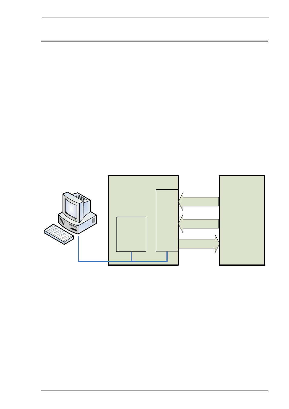
5.01 Robot Interface INT06
The Robot interface INT06 is for connection between the PowerMaster 400SP/500SP Automation power
sources and the robot control. There are different analog and digital in-outputs available to allow an individual
adaptation between welding power source and robot control.
Configuration of the INT06 is possible via:
• The control panel of the power source
• A PC with CAN interface
The INT06 works as a participant of the internal CAN-Bus. Commands coming over the INT06 interface are
converted into CAN-Bus messages and vice versa: actual values and status signals coming from the internal
CAN-Bus (e.g. "welding current on") are put out to the INT06 interface.
The INT06 is potentially separated from the machine. The analog and digital inputs are not potentially separated
from each other.
All inputs and outputs are available at the 42-pin Harting socket at the rear side of the welding power source.
Additional signals and functions (like gas monitoring) can be connected optionally.
Digital
Power
Source
INT06
µP
CAN-Bus
CAN-Bus
Art # A-07825
Robot Control
Analog
Digital
5.02 Digital Inputs and Outputs
The 18 digital inputs are designed for a voltage of +24V DC. For some of the digital inputs, LEDs are showing
the state of the inputs (see "Overview LEDs Robot interface INT06" on page 4).
The two digital outputs are designed as potential free relays contact. The power rating of the contacts is max.
1A at 48V. The state of the digital outputs are displayed on the pc-board INT06 with two LEDs (see " Connec-
tors on Robot Interface INT06 PC Board" on page 5-3).