07 quick start set up, 08 recommended setup for mig – Tweco 500SP PowerMaster Automation User Manual
Page 31
POWERMASTER 400SP, 500SP AUTOMATION
March 16, 2007
3-7
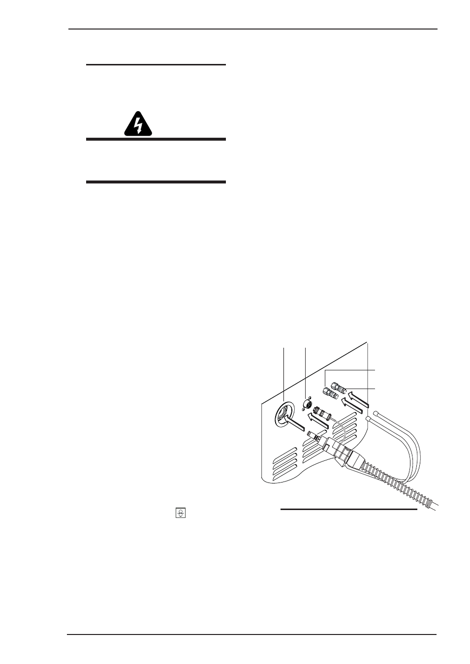
3.08 Recommended Setup for MIG
A. Torch Connection (TWECO
PulseMaster PMA5 shown as an
example)
1. Open the door panel to the machine by
turning the release knobs and pulling the
cover outward and up.
2. Route the gun cable through the access hole
in the front panel.
3. Locate the thumbscrew on the gun adapter
inside the unit. Loosen the thumbscrew and
insert the gun cable end into the gun adapter
as far as it will go. Tighten the thumbscrew.
4. Align the keyways of the gun switch
connector with the trigger receptacle next to
the gun cable and plug them together. Secure
by turning the locking ring to the right
(clockwise ).
5. If a coolant cooling system is installed,
connect the coolant hoses of the torch with
the coolant sockets on the front panel. Be
sure to connect the red fittings together and
the blue fittings together.
Art # A-07851
Trigger Receptacle
Front Panel
Access Hole
Hot coolant return
(Red)
Cool coolant to torch
(Blue)
3.07 Quick Start Set Up
NOTE:
Please refer to Sections 3.04 Recommended
Equipment Setup and SECTION 4: Control
Panels for explanations of the controls.
WARNING
Thermal Arc advises that a suitable Mains
Plug be fitted to this equipment by a
qualified electrical trades-person.
A. Where equipped, place the gas cylinder on the
power supply cylinder tray and secure with the
two safety chains. If unit is not equipped with this
option, then ensure that the gas cylinder is secured
to a building pillar, wall bracket or otherwise
securely fixed in an upright position.
B. Remove screw cap from gas cylinder, if fitted, and
open gas cylinder valve briefly to remove
contaminants.
C. Connect gas regulator to gas cylinder.
D. Connect gas hose from power supply to gas
regulator and open gas cylinder valve.
E. Connect input power, refer to previous WARNING
and the Connecting Input Power Section.
F. Connect work lead to Negative connection (–) and
attach Work clamp to workpiece.
G. Fit the correct size feed rollers to wire feeder then
fit the selected welding wire and set the pressure
levers to position 2.
H. Connect torch (central socket, coolant connections
red-blue) and mount contact tip to fit welding wire
selected.
I. Insert welding wire.
J. Turn on main switch.
K. Press push-button and push-button (gas type)
(solenoid valve is activated) and adjust gas amount
on the gas regulator.
L. Keep the wire inch switch
pressed until the
welding wire protrudes approximately 3/8 inch (10
mm) out of the MIG torch nozzle.
NOTE
When disconnecting gun switch leads
from the machine, loosen the locking ring
and grab the connectors and pull. Do not
pull on the wires.
6. To remove the gun, reverse these directions.