Section 3: installation, 01 location, 02 transportation and positioning – Tweco 500SP PowerMaster Automation User Manual
Page 25: 03 fitting the mains cable into the cable gland, Section 3, Installation -1
POWERMASTER 400SP, 500SP AUTOMATION
March 16, 2007
3-1
SECTION 3:
INSTALLATION
NOTE
Please refer to Sections 3.08 Recommended
Equipment Setup and SECTION 4: Control
Panels for explanations of the controls.
!
WARNING
Thermal Arc advises that a suitable Mains
Plug and cable be fitted to this equipment
by a qualified electrical trades-person.
3.01 Location
Adequate air circulation is needed at all times in order
to assure proper operation. Provide a minimum of 12
inches (305 mm) of free airspace on all sides of the
unit. Make sure that the ventilator openings are not
obstructed. Ventilation airflow is from rear to side.
3.02 Transportation and Positioning
Properly transporting and positioning the equipment
is important for preventing injury. Move the equipment
in an upright position and pick a flat welding surface.
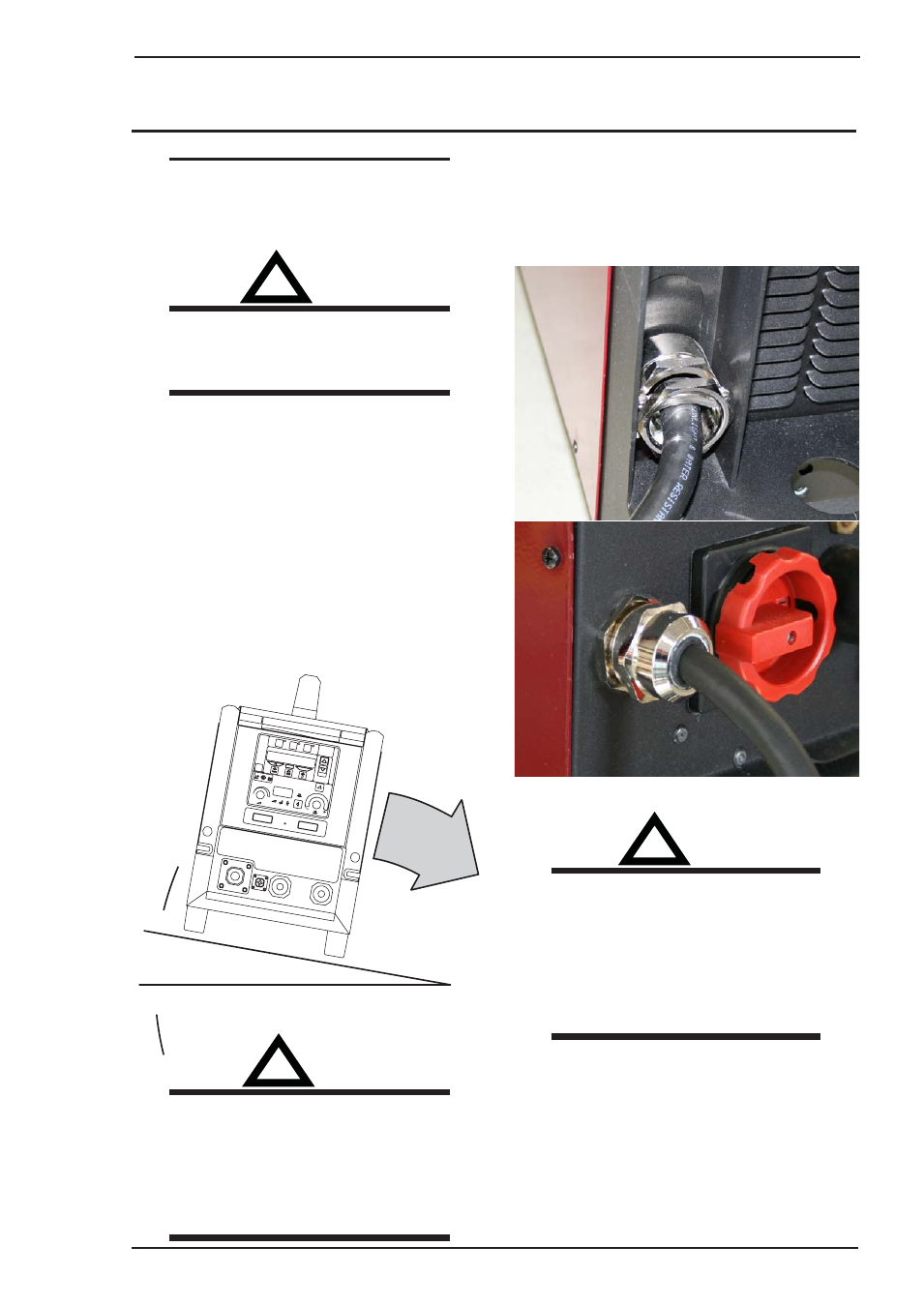
3.03 Fitting the Mains Cable into the
Cable Gland
Refer to the pictures below when connecting the
mains cable to the cable gland.
(END)
(END)
(+)
(+)
mm
mm
Save
Save
Enter
Enter
Enter
Enter
Mode
Mode
Tiptronic
Tiptronic
V
HOLD
HOLD
A
Art # A-08324_AA
Art # A-08325_AA
!
WARNING
The mains cable has to be assembled into
the cable gland as shown in the picture.
The electrical technician has to make sure
that the cable gland is adjusted to the
external diameter of the mains cable and
the mains cable is securely fastened in the
cable gland according to IEC 60974-1.
!
WARNING
Injury to the operator may occur if the
machine’s maximum permissible angle of
inclination is exceeded. The maximum
permissible angle of inclination is 10°. Only
transport or position the machine for
welding on a flat and level surface.