Tweco 500SP PowerMaster Automation User Manual
Page 39
POWERMASTER 400SP, 500SP AUTOMATION
March 16, 2007
4-3
(55) “Primary parameter” indicator lights
These lights show which primary parameter
is currently displayed in the multifunction
display (54).
(56) “Primary parameter” push-button
For switching between welding current,
material thickness, wire feed speed and arc
length, as indicated in the digital multifunction
display (54).
(57) “Downslope” push-button
Switches the downslope function on or off. A
lit LED next to the push-button indicates that
the downslope is on.
(58) “Arc length” control knob
To adjust the arc length in SmartGMAW,
PulseGMAW,
process,
OR
"Wire speed/Inductance" control knob. To
adjust the wire speed or Inductance in Manual
MIG process.
(59) “Arc length” LED indication
Indicates the degree of the trim in
SmartGMAW, Pulse MIG,
process.
OR
”Wire speed” LED indication Indicates the wire
speed in ManualGMAW process.
When the uppermost center LED is lit, the
programmed arc length/wire speed remains
unchanged; “0” is indicated in the
multifunction display (54). Turn the rotary
control knob (58) left to shorten the arc length/
wire speed; turn the rotary control knob (58)
right to lengthen the arc length/wire speed.
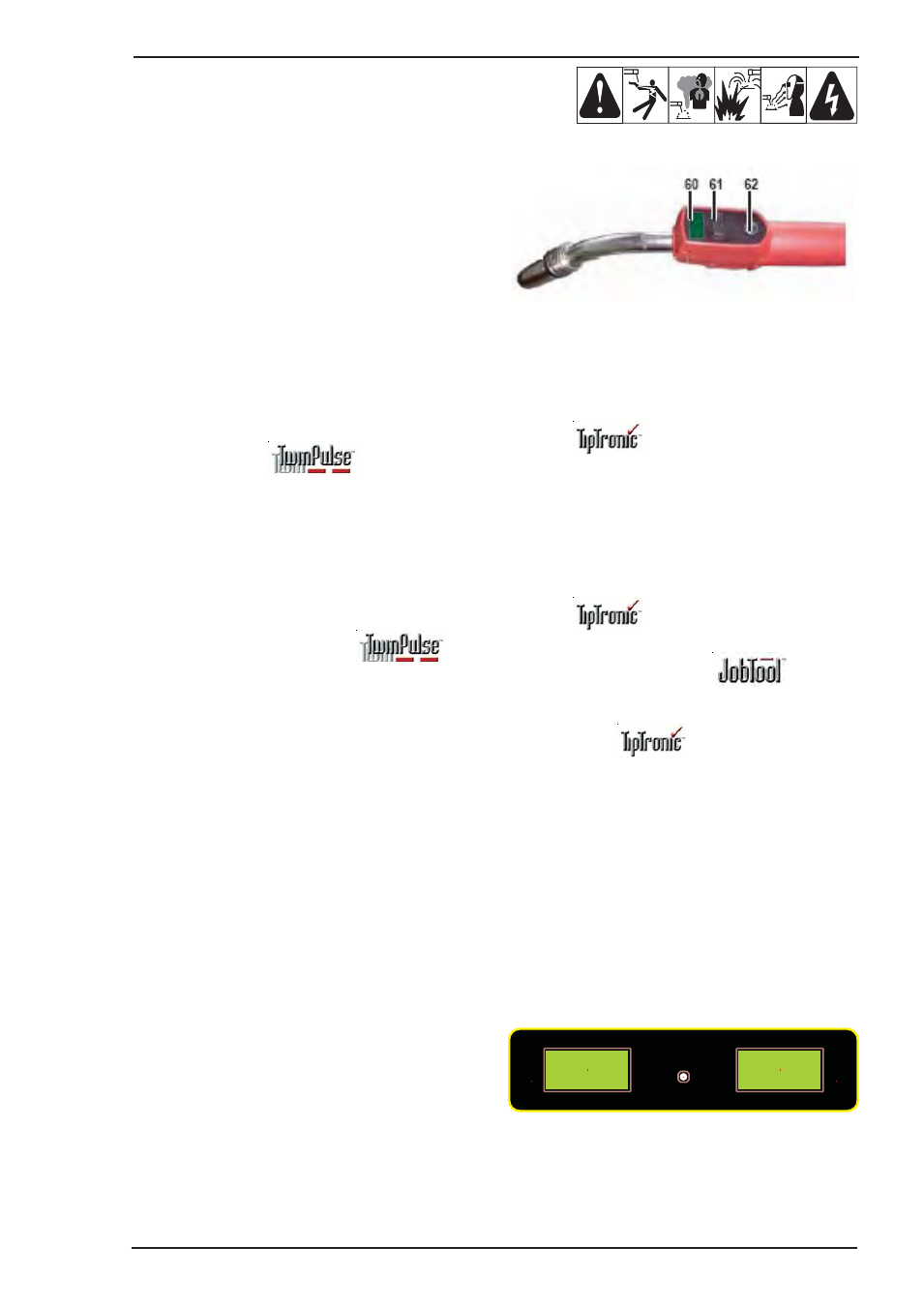
Art # A-06376
(60) Smart Torch display
Indicates the welding current or arc length trim;
material thickness or arc length trim; wire feed
speed or arc length trim (Linked to the digital
multifunction display (54)).
In
process, the current job set and
the current job number are displayed.
(61) Smart torch rocker
Changes the welding current, material
thickness, arc length to the arc length
(depending on which value is being displayed
on the digital multifunction display (54)).
In
process, the rocker can be used
to switch between the active jobs or job sets.
(62) Smart torch push-button
Has the same function as the “Primary
parameter” push-button (56) on the
Control
Panel
. In
process this push-button
can be used to switch between job selection
and job-set selection.
Current / voltage display
The actual welding voltage and welding current values
are indicated during welding. After the welding
procedure, the “Hold” LED illuminates and the last
welding voltage and welding current values are
indicated. When the operator changes certain welding
adjustments (e. g. thickness, program, job), the
“Hold” LED goes out and the preview values for
current and voltage are displayed.
V
HOLD
TENIR
A
Art # A-07865