03 menu structure, 03 menu structure -4 – Tweco 500SP PowerMaster Automation User Manual
Page 40
POWERMASTER 400SP, 500SP AUTOMATION
4-4
March 16, 2007
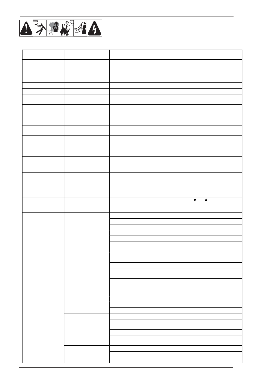
4.03 Menu Structure
Main Menu
Level 1 “Extras”
Level 2
Remark
Gas pre-flow
0
–
10
sec.; not in SMAW/STICK electrode process
Start current
20
% – 200 % of the welding current
Start current time
0 – 10 sec.; not in 4-stroke (4T) mode
Twin pulse frequency
0,5 – 5 Hz; only in TwinPulse mode
Twin pulse current change
5
–
50
% of the welding current; only in TwinPulse process
Twin pulse relation
20
% – 80 %; only in TwinPulse process
Welding current
Adjustment range depends on the selected material-wire-
gas combination
Downslope
10
–
990
A/sec.; not in SMAW/STICK process, only when
downslope = on
Crater fill current
10
% – 200 % of the welding current; not in SMAW/STICK
process, only when slope = on or in 4 (4T) stroke
Crater fill time
0 – 10 sec.; not in SMAW/STICK process, only for slope =
on
Wire burnback
time
20
% – 300 % of the programmed value; not in
SMAW/STICK process
Gas post-flow
20
% – 200 % of the programmed value; not in
SMAW/STICK process
Arc length correction
60
% – 140 % of the programmed value
Inductor
effect
20
% – 200 % of the programmed value; only in
ManualGMAW process (short arc)
Arc dynamic arc force
0
% – 100 % of the programmed value; only in
SMAW/STICK process
Job selection, indication of
set and job name
Set and job name are indicated only in Tiptronic mode upon
actuation of the „TT Enter“ push-button (47) or the
„Tiptronic“ push-button (49)
Edit
mode
for set and job
name
Move the cursor with the
and
push-buttons (51);
change the character with the pushbuttons (48) (+) and
(44) (-)
Operating system Master Version number, operating system Master
Operating system Process Version number, operating system process
Operating system DMRs Version number, motor assembly
Welding program version Version number, welding programs
Operating hour counter
Indication of the welding duration in h, min, sec
1 Machine data
Configuration Machine type and the recognized power module (with max.
current ) are indicated alternately
Last error message Indication of the last three error messages from the error
memory (0 = last error, 2 = oldest error)
Module temperatures Temperatures of the power modules in °C
Operating voltages
Indication of the operating voltages (15 V
/ 24 V) of the
assembly DPMAPRO
2 Diagnosis
Flow rate, cooling unit Indication of the coolant flow rate in l/min
3 Language
Selection of the menu language
4 Display contrast
Contrast setting of the LCD display
0 normal cooling unit switches on, as soon as an arc is ignited
1 on cooling unit runs constantly
5 Mode cooling system
2 off
cooling unit is deactivated
0 All
welding controls can be adjusted by user
1 Only Tiptronic on/off and job selection can be adjusted by
user
2 Tiptronic on/off, job selection free
6 Lock function
3 All
welding controls locked except menu selection, gas and
pump test
Voltage correct arc length with rotary pulse encoder (58)
7 Arc length control
Wire correct wire speed with rotary pulse encoder (58)
Extras
8 Robot interface
Menu item is only visible when the machine is equipped