Tweco 500SP PowerMaster Automation User Manual
Page 33
POWERMASTER 400SP, 500SP AUTOMATION
March 16, 2007
3-9
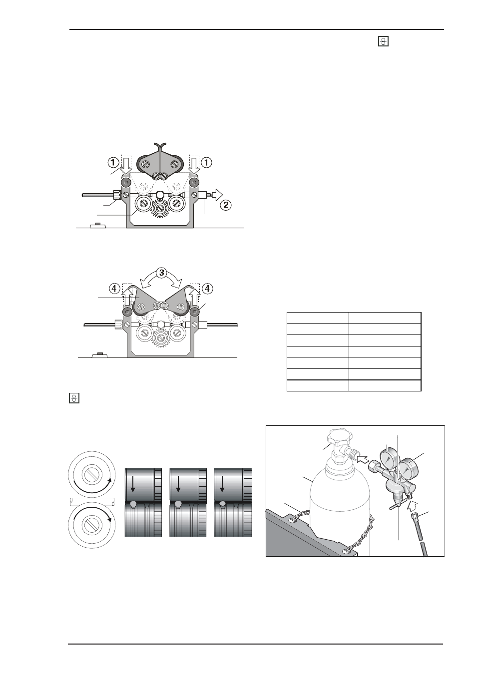
F. Insertion Of The Wire Electrode
Screw out the contact tip in the MIG torch handset.
Open the wire feed compartment lid on the power
supply or wirefeed case.
The diameter of the wire should correspond to the
diameter of the feedrolls. The wire size is on the face
of the feedrolls. Open the pressure lever and thread
the wire through the inlet guide and the outlet guide.
Art # A-06369
Pressure lever
Outlet guide
Inlet guide
Feedroll
Close the lever and fasten the pressure rollers.
Art # A-06370
Lever
Pressure
adjustment
screw
Switch on power supply at main switch, stretch torch
cable out straight and press the inch switch button
in the wire feed compartment. Adjust the pressure
at the pressure adjustment screws so the wire-feed
rolls drive the wire consistently without slipping. The
wire should not be deformed.
p
p
p
Correct
Pressure
Pressure
too High
Wrong Size
Feedrolls
Art # A-06371
Adjust the pressure adjustment next to the inlet guide
to a lower pressure less than the pressure adjustment
next to the outlet guide, this will ensure that the wire
will be located correctly in the wire-feed unit.
Press the inch switch button
until the wire
appears approximately 3/4 inch (20 mm) out of the
torch neck.
Screw in the contact tip corresponding to the wire
diameter and cut off any wire sticking out.
G. How To Connect The Gas Cylinder
If the Wheeling Kit option has been installed, position a
gas cylinder on the rear tray and lock securely to the
Power Source cylinder bracket with the chains provided.
If this arrangement is not used then ensure that the
gas cylinder is secured to a building pillar, wall bracket
or otherwise securely fixed in an upright position.
Open the gas valve once to blow out possible dirt
particles.
Connect the gas regulator to the gas cylinder valve.
Connect the gas hose to the gas regulator.
Open the gas cylinder valve and adjust the gas flow on
the gas regulator while pressing the torch trigger switch.
The quantity will be shown at the flowmeter.
This should be approximately:
Wire Size (in)
Gas Flow (CFH)
.023
13
.030
17
.035
19
.040
21
.045
25
3/64
34
gas regulator
gas cylinder valve
gas cylinder
bracket chain
input gauge
output gauge
gas hose
regulator valve
Art # A-06372
2
33
32