Tweco Weld Sequencer User Manual
Page 55
Manual 0-2023
49
APPENDIX
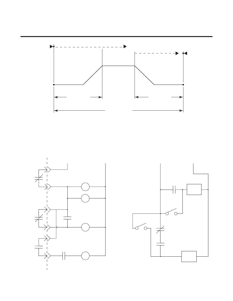
APPENDIX I: MOTION CONTROL & WIRE FEED
INTERFACE DIAGRAM
Start Of
Sequence
End Of
Sequence
TD2
TD1 or TD3
Peak Weld
Current
Final
Current
Do
wnslope
Upslope
AL Deenergized
AL Energized
AL Deenergized
AL Energized
CC Energized
CC Deenergized
CC Energized
AL Deenergized
Initial
Current
NOTE:
TD1 and TD3 are customer supplied adjustable time delay
relays used to delay the start of motion or wire feed controls
at any point during the Initial Current, Upslope, or Peak Current
sequence.
TD2 is a customer supplied adjustable time delay relay used
to stop the wire feed control at any point during the Downslope or Final
Current sequence.
CC Relay operates only with CS1 or WT1.
AL Relay operates only with CS1.
TD1 - Wire Feed Start
TD2 - Wire Feed Stop
TD3 - Motion Start
TD1, TD2 and TD3 are customer supplied adjustable 115 VAC time delay relays (delay on operate).
Latch Relay, LR, is necessary to provide proper sequence of time delay relays TD1, TD2 and TD3.
TD2
TD3
LR
TD1
Input Power For TD Relays
CC
AL
AL
LR
LR
Weld Sequencer
Enclosure
Customer Supplied
Motion
Device
Wire
Feed
Input Power For Motion Control Device
And Wire Feed
TD3
TD2
TD1
Motion
Wire
A-02448