07 cp1 pulser control descriptions, Figure 4-6 cp1 pulser – Tweco Weld Sequencer User Manual
Page 28
OPERATION
22
Manual 0-2023
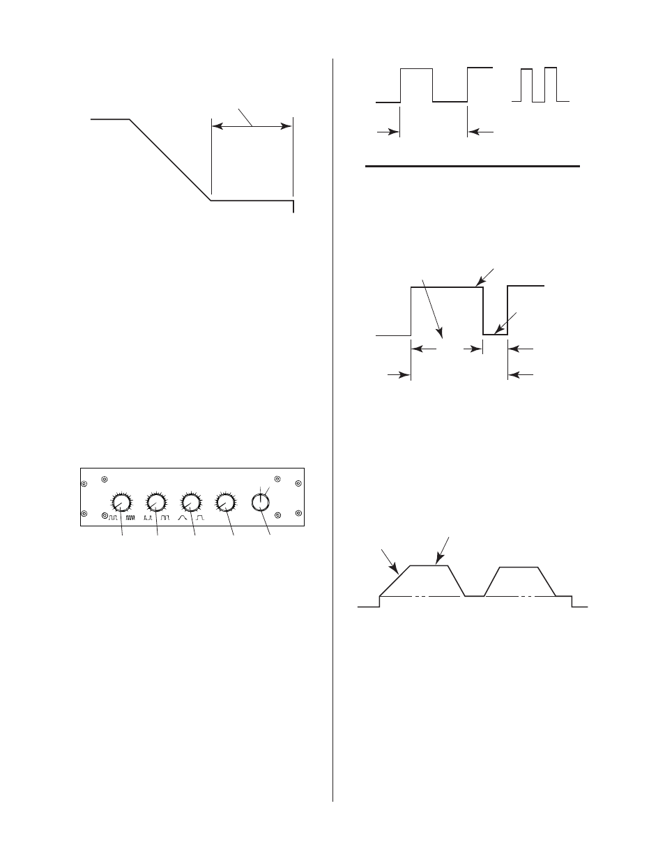
5. FINAL CURRENT/TIME Control
F i n a l C u r r e n t
T i m e
A - 0 2 4 2 5
A dual control potentiometer that controls the Final
Current and the Time. The FINAL CURRENT con-
trol (inner knob) sets welding current at the finish of
the weld. Like the INITIAL CURRENT it is a per-
centage of the set operating current range of the Power
Supply (maximum current setting determined by RP1)
and is added to the minimum current to arrive at a
amperage value.
The FINAL TIME control (outer knob) sets the length
of time that the final current will be maintained be-
fore signaling the contactor to open, ending the weld.
The numbers around the knob refer to seconds.
4.07 CP1 Pulser Control
Descriptions
CP1
PULSER
A - 0 2 4 1 9
O N
O F F
0
1
2
3
4
5
6
7
8
9
1 0
P U L S E R AT E
0
1
2
3
4
5
6
7
8
9
1 0
P E R C E N T O N T I M E
0
1
2
3
4
5
6
7
8
9
1 0
P U L S E S L O P E
0
1
2
3
4
5
6
7
8
9
1 0
BAC K G RO U N D C U R R E N T
( p u l l fo r d i s p l ay )
1
2
3
4
5
Figure 4-6 CP1 Pulser
1. ON/OFF Switch
In OFF position CP1 is disabled. In the ON position
its circuitry is energized.
2. PULSE RATE Control
Regulates the number of pulses (time taken to go from
point A to point B) in a given time period. Numbers
are for reference only and do not indicate pulses per
second.
A - 0 2 4 2 6
A
B
A
B
O n e P u l s e
T i m e
EXAMPLE
Ten pulses in one second means that the distance
from point A to point B is traveled ten times in one
second (10 pulses/second or 600 pulses/minute)
3. PERCENT ON TIME Control
A - 0 2 4 2 7
O n e P u l s e
Pe r c e n t O N
T i m e S e t t i n g
Pe a k C u r r e n t
B a ck gr o u n d
C u r r e n t
7 5 %
2 5 %
Sets the amount of time the peak current is on relative
to the amount of time background current is on, in
any one pulse. Settings are in percent, not actual time.
A setting of 50% means peak current is on the same
amount of time as the background current. A setting
of 75% means peak current is on three times longer
than background current.
4. PULSE SLOPE Control
Pe a k C u r r e n t
G ra d u a l
C h a n g e
B a ck gr o u n d C u r r e n t
A - 0 2 4 2 8
Allows gradual change in current between back-
ground current and peak current levels during puls-
ing.
5. BACKGROUND CURRENT Control (pull for dis-
play)
Adjusts lower level of current. Can be adjusted while
pulsing by turning the knob. Numbers around knob
refer to the percentage of Power Supply output cur-
rent range and should not be taken as an amperage
value.