09 pre-operation setup – Tweco Weld Sequencer User Manual
Page 30
OPERATION
24
Manual 0-2023
4.09 Pre-Operation Setup
A. General
1. Follow all pre-operation set-up procedures required
in the Welding Console and Power Supply instruc-
tion manuals.
2. Move the ON/OFF switch on the Weld Sequencer En-
closure to the ON position.
WARNING
The RP1 Control CONTACTOR ON/OFF switch
must be in the OFF position before the Weld Se-
quencer Enclosure or any control module is shut
off. If this is not done and the torch is close enough
to the workpiece (or ground) when the system is
energized an arc transfer can take place.
CAUTION
Pre-operation setup of each module can be done in-
dependently from the others but it must be kept in
mind that when actual welding sequence begins
some controls depend on others for proper opera-
tion. For instance, the rate of plasma gas flow must
correspond to the current level at any given time
or tip damage could occur.
3. If GS1 is installed but not being used, set gas flow with
GS1 first then turn GS1 OFF.
4. CS1 and CP1 controls are adjusted within the current
range selected on the power supply (determined in
Step 1). Some control settings can be made only by
trial and error during sample welding operations.
B. CS1 Current Slope
CAUTION
The sloping current must stay within the accept-
able range of plasma gas flow rate to prevent tip
damage (current too high) or insufficient penetra-
tion (current too low).
1. Move the ON/OFF switch to the ON position.
2. Set the starting current from which upslope will begin
and the percentage of difference between adjusted
MAX (as set on RP1 WELD CURRENT) and MIN of
the power supply range and adjust the inner knob
(INITIAL CURRENT) to obtain the desired current
level.
NOTE
Initial current must be within the range selected
on the power supply.
EXAMPLE
A. The power supply is set in a range of 25 to 125
amps and the desired initial current is 30 amps.
This value is 5 amps above the MIN range of
25 amps (30-25 min = 5).
B. Full current range is 125 amps MAX - 25 amps
MIN = 100 amps.
C. The 5 amps above MIN (25 amp) setting di-
vided by the 100 amp range equals the percent-
age setting of the INITIAL CURRENT (inner)
knod (5 ÷ 100 = 0.05 or (5%). Set knob on 5
(5%).
3. Set initial current time from 0 to 10 seconds using the
outer knob on the INITIAL CURRENT/TIME control.
The numbers correspond directly to the time in sec-
onds.
4. Set final current at which downslope will end. Final
current value is determined the same as in Step 2
above and is set using the inner FINAL CURRENT
knob.
5. Adjust UPSLOPE RATE control while test welding until
the desired upslope is obtained or use Figure 4-8. Note
the number corresponding to the knob position for
future reference.
6. Adjust DOWNSLOPE RATE control while test weld-
ing until the desired downslope is obtained (or use
Figure 4-8). Record the number corresponding to the
knob position for future reference.
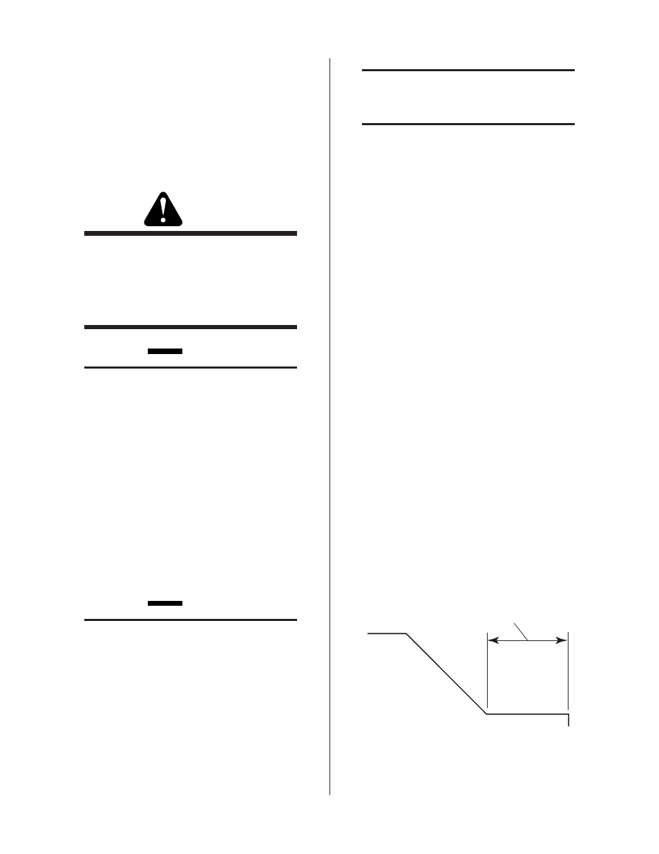
7. Set final current time from 0 to 10 seconds using the
outer knob on the FINAL CURRENT/TIME control.
The numbers correspond directly to the time in sec-
onds.
F i n a l C u r r e n t
T i m e
A - 0 2 4 2 5
8. Adjust DOWNSLOPE DELAY (inner) knob to the de-
sired delay 0 to 10 seconds as indicated by the num-
bers.