Tweco Weld Sequencer User Manual
Page 41
Manual 0-2023
35
Section Name
A-02440
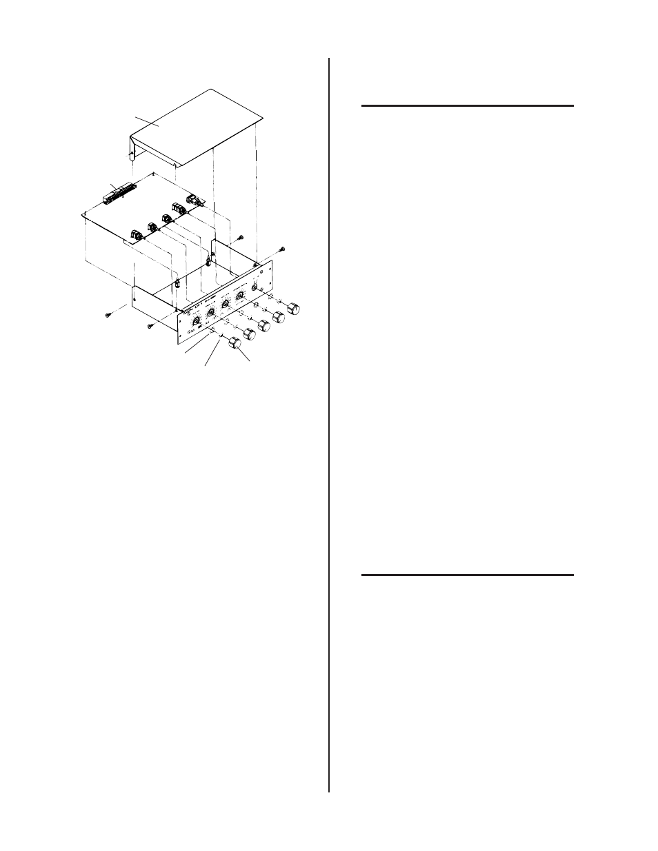
Knob
Hex Nut
Washer
PC Board
Connector
Cover
Figure 5-4 Typical PC Board Removal
4. Remove all the hex nuts securing Figure 4-D Typical
PC Board Removal (CP1, CS1 and GS1)
5. Press the locking tab on each PC board support and
raise the board past the locking position to allow re-
moval of the board.
6. Install the PC board (component side up) into the
switch mounting holes in the front panel. Press the
board down onto the supports until it snaps into the
locking tabs.
7. Secure the switches to the front panel with supplied
hex nuts.
8. Position knobs on the flats of the switch shafts and
push on.
9. Connect plug(s) to connector(s).
10. Replace module cover and secure.
D. GS1 Motor/Valve/Pot Assembly
Replacement
NOTE
Refer to Sections 6.04 and 6.05 for parts list and
overall detail drawing.
The main components of the Motor/Valve/Pot Assem-
bly are replaceable. These include the motor assembly,
valve assembly, pot assembly, pinion gear, and coupling.
The assembly can also be purchased complete. Replace-
ment of the components require that GS1 be removed
from the Weld Sequencer. Proceed as follows:
1. Disconnect all power to the welding system.
2. Remove cover or side panels (enclosure extension).
3. Remove the two welding console plasma gas hoses
from the rear of the Weld Sequencer Enclosure. Re-
move the four screws holding the GS1 gas hose con-
nectors to the Enclosure rear panel.
4. Remove connector from the rear of GS1.
5. Remove the four screws securing GS1 to the front of
the Weld Sequencer Enclosure.
6. Slide GS1 out of the Weld Sequencer Enclosure.
7. Remove the cover from GS1.
8. Disconnect the two connectors (motor and pot) on the
Motor/ Valve/Pot Assembly.
9. Remove the four screws securing the Assembly to the
GS1 rear panel.
If the complete Motor/Valve/Pot Assembly is to be
replaced go to Section 5.05-H.
E. Coupling, Pinion Gear, Pot Assembly and
Motor Assembly Replacement
NOTE
Refer to Section 6.05 for parts list and overall de-
tail drawing.
1. If the motor assembly is to be replaced loosen the two
1/16" hex set screws securing the coupling to the
motor assembly. If the coupling or pinion gear is to be
replaced loosen the two 1/16" hex set screws secur-
ing the coupling to the pinion gear.
2. Remove the four screws from the motor assembly and
remove the motor and coupling, leaving the pinion
gear in place