04 test procedures, A. checking wt1, B. checking contactor control – Tweco Weld Sequencer User Manual
Page 39: C. checking current control
Manual 0-2023
33
Section Name
R. Using RP1 and CP1, spot welds are erratic with
varying penetration
1. CP1 on during spot welding
a. Turn CP1 to OFF
When the CS1 FINAL TIME times out the CC relay is
energized, opening the circuit to the main contactor in
the power supply. Welding arc is extinguished.
S. Welding arc does not extinguish
1. CC relay faulty
a. Replace relay
2. CS1 PC Board faulty
a. Replace
At the end of the weld the RP1 CONTACTOR switch is
moved to the OFF position first to open the main con-
tactor in the power supply. Then the Weld Sequencer
Enclosure is turned OFF along with the other compo-
nents of the system.
T. Welding arc transfers when CS1, WT1 or Weld
Sequencer is turned OFF
1. RP1 CONTACTOR switch not OFF
a. Move RP1 to OFF
5.04 Test Procedures
WARNING
Some tests involve voltage measurements made
with power ON. Tests requiring voltage measure-
ments are marked with this warning symbol. All
other tests are to be made with the primary system
power turned OFF.
The following tests are suggested for specific problems
listed in the troubleshooting guide. Letter designations
correspond to those listed in the remedy area of the guide.
A. Checking WT1
To test WT1 move the torch to about 1 inch (25.4 mm)
above the workpiece. Arc will not transfer but the gas
should go through the upslope sequence to max flow and
start to downslope at the end of set weld time (or at end
of downslope delay time). If this does not happen WT1
is faulty and must be replaced.
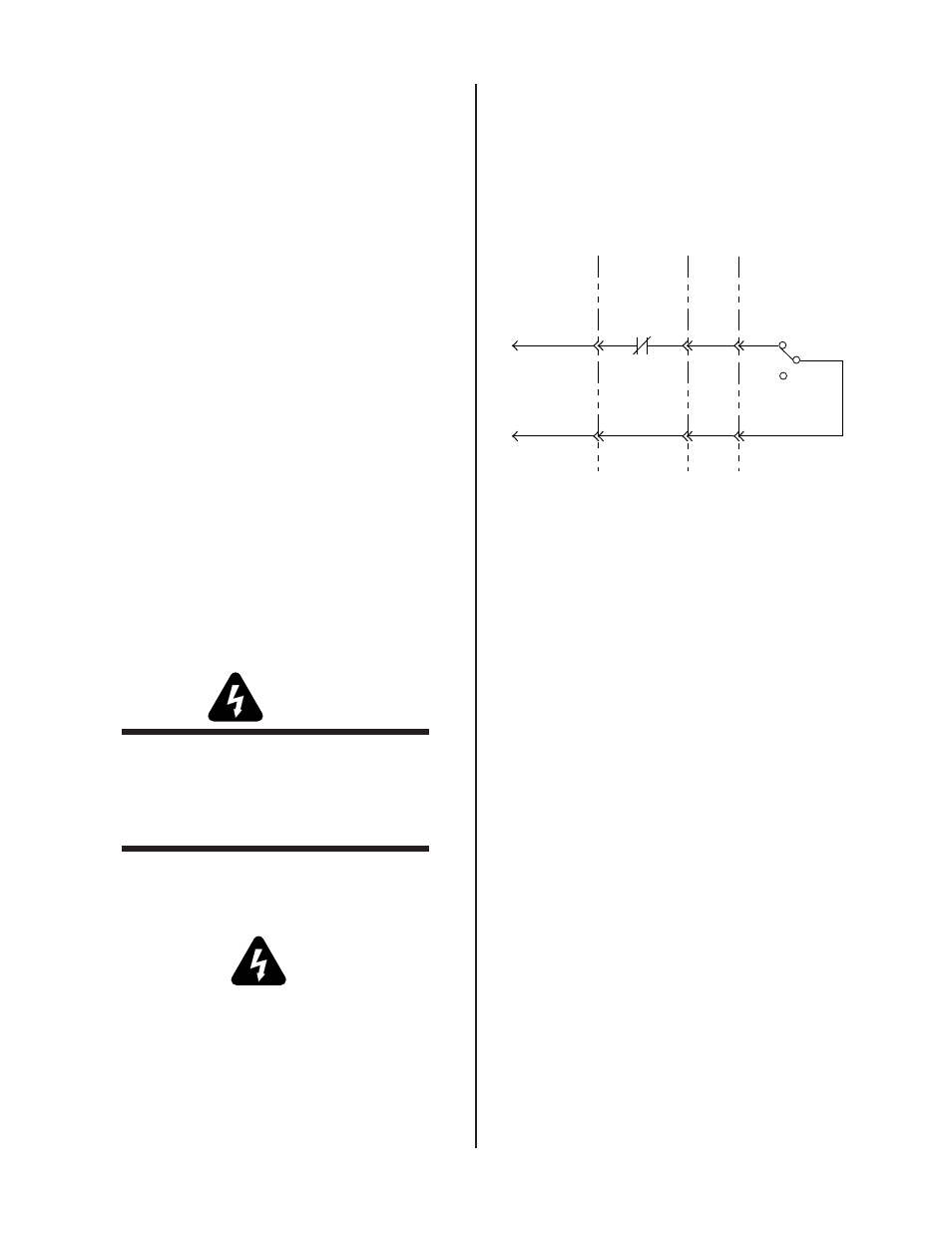
B. Checking Contactor Control
With the Weld Sequencer in OFF position and the RP1
CONTACTOR switch ON. Use an ohmmeter to check
for continuity from black to white/brown wires on the
console P/S cable J5-4 and J5-5. If there is no continuity,
check each component and wire in the contactor control
circuit diagram.
Black
White/Brown
A-02438
CC
ON
OFF
Contactor
26
28
28
26
27
J5-4
J5-3
J6-4
J6-3
J9-4
J9-3
Console/Power
Supply Control
Cable
Weld
Sequencer
Enclosure
Remote
Control
Cable
RP1
Figure 5-2 Contactor Control Circuit Diagram
C. Checking Current Control
With CS1 and CP1 turned OFF or J8 and J7 connected to
the jumper plugs and RP1 CURRENT CONTROL set to
minimum, check for continuity (approximately zero
ohms) from J5-7 (red wire) to J5-13 (blue wire), (refer to
Figure 5-3) with an ohmmeter set on “times 1000” scale.
Check for 10K (10,000) ohms from J5-7 to J5-1. Setting
RP1 CURRENT CONTROL to maximum will reverse the
readings (zero ohms between J5-7 and J5-1, and 10K ohms
between J5-7 and J5-13). If proper readings are not ob-
tained check individual wire connections and components
to identify the fault.