06 gs1 gas slope – Tweco Weld Sequencer User Manual
Page 21
Manual 0-2023
15
INSTALLATION PROCEDURES
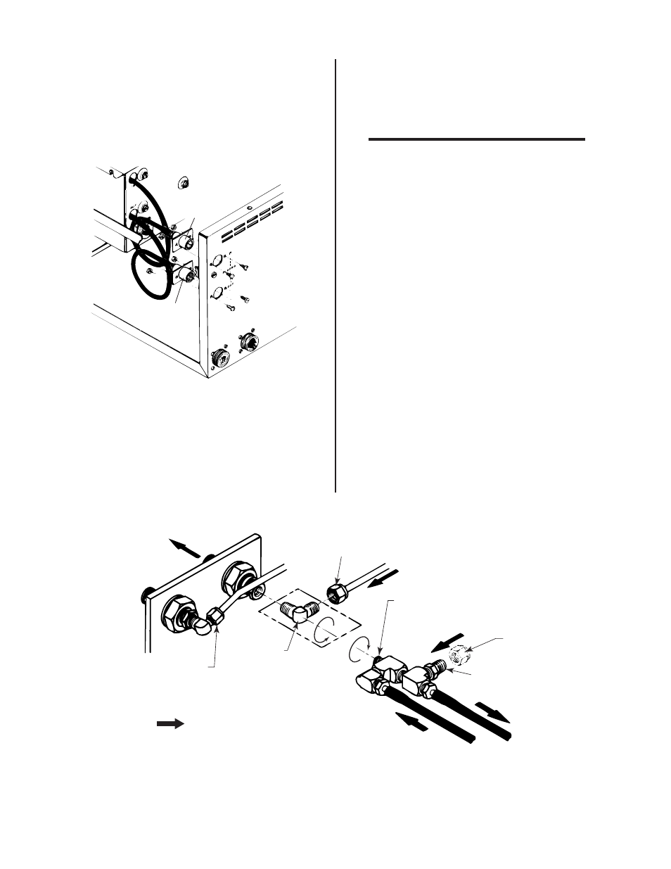
3.06 GS1 Gas Slope
1. Install PLASMA IN and OUT fittings from the back of
GS1 through the opening in the front of the Weld Se-
quencer Enclosure and secure to the rear of the Enclo-
sure.
P L A S M A
G a s I N
P L A S M A
G a s O U T
A - 0 2 4 1 0
Figure 3-7 GS1 Plasma Connections
2. Install GS1 into upper opening of the Enclosure (refer
to Figure 3-6) and secure with screws provided.
3. Connect GS1 to the Weld Sequencer Enclosure wiring
harness with the J3 connectors.
NOTE
If CS1 and/or CP1 are not used then the jumper
connectors must be installed in wire harness con-
nector J8 (CS1) and/or connector J7 (CP1). If this
is not done the current control will not function
properly.
4. Install GS1 adapter fitting assembly into the welding
console between the flowmeter and the plasma gas
torch connection. For installation in Welding Consoles
WC100A, WC100B and WC122A (refer to Figures 3-8,
3-9, and 3-10).
5. Feed plasma gas hoses from the adapter fitting assem-
bly through the plastic bushing on the rear panel of
the welding console.
6. Open plasma gas flow valve on the welding console
all the way.
To To rch
D i s c o n n e c t t h i s t u b e
a n d m ove u p a n d o u t
o f t h e way. R e c o n n e c t
a f t e r a s s e m bl y i s c o m p l e t e.
1 .
R e m ove
t h i s f i t t i n g .
3 .
D i s c o n n e c t Tu b e
2 .
A d d s e a l a n t t o t h r e a d s a n d s c r ew
i n a s s e m bl y t o p o s i t i o n s h ow n .
4 .
F ro m P l a s m a G a s M e t e r i n g Va l v e
F ro m S o u rc e
R e m ove
t h i s nu t .
5 .
R e c o n n e c t p l a s m a
g a s s u p p l y h o s e.
6 .
To G S 1
F ro m G S 1
B o l d a r r ow s i n d i c a t e d i r e c t i o n o f f l ow
A - 0 2 4 1 1
Figure 3-8 GS1 Connections to WC100A and WC122A (with copper tubing)