08 gs1 gas slope control descriptions, Figure 4-7 gs1 gas slope – Tweco Weld Sequencer User Manual
Page 29
Manual 0-2023
23
OPERATION
EXAMPLE
A Power Supply set in a range of 50 - 150 amps
with a background current of 30% would be 150 -
50 = 100 amps total range 100 amps x 30% = 30
amps 30 amps + 50 amps min = 80 amps back-
ground.
B a ck gr o u n d C u r r e n t
A - 0 2 4 2 9
;;;;
To adjust background current with an ammeter while
doing a test weld, pull the knob out. CP1 will cease to
pulse and will maintain weld current at background
current level. Adjust to new background current by
turning knob (checking ammeter on console or power
(supply). Push back in to resume pulsing operation.
NOTE
An auxiliary connection is available to start or stop
the CP1 without stopping the weld sequence (see
AVC LOCKOUT, refer to Section 3.09).
4.08 GS1 Gas Slope Control
Descriptions
GS1
GAS SLOPE
M I N
G A S F L OW
. 5 - 3 S C F H
. 2 5 - 1 . 4 l p m
M A X
G A S F L OW
2 - 7 S C F H
1 - 3 . 3 l p m
0
1
2
3
4
5
6
7
8
9
1 0
0
1
2
3
4
5
6
7
8
9
1 0
U P S L O P E
R AT E
0
1
2
3
4
5
6
7
8
9
1 0
D OW N S L O P E
R AT E
0
1
2
3
4
5
6
7
8
9
1 0
D OW N S L O P E
D E L AY
( 0 - 1 0 s e c . )
0
1
2
3
4
5
6
7
8
9
1 0
A - 0 2 4 2 0
G A S F L OW
M I N
S L O P I N G
M A X
U P
D OW N
M A N UA L
AU TO
O N
O F F
1
2
3
4
9
8
7
6
5
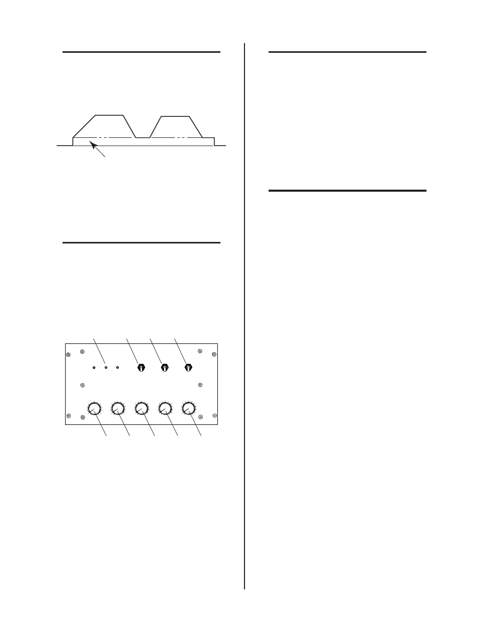
Figure 4-7 GS1 Gas Slope
1. ON/OFF Switch
In OFF position GS1 is disabled and gas flow remains
at its last setting. The ON position energizes its cir-
cuitry.
2. MANUAL/AUTO Switch
MANUAL position allows the operator to manually
control gas slope sequence for setup and also during
the welding operation.
NOTE
CS1 will not operate with GS1 in MANUAL posi-
tion. In AUTO position the gas slope sequence will
automatically be controlled by signals from the CS1
Control circuitry only.
3. UP/DOWN Switch
With the MANUAL/AUTO switch in MANUAL po-
sition the UP/DOWN switch (see NOTE) is used to
start upslope (UP) and downslope (DOWN) of gas
flow. The rate of slope is determined by the sloping
control settings. In AUTO position, the UP/DOWN
switch is disabled.
NOTE
Refer to Section 4.04, RP1 Control, for Remote
Up/Down Control.
4. GAS FLOW MIN/SLOPING/MAX LED
These three LEDs light to indicate the status of gas
flow during a weld.
5. MIN GAS FLOW Control
Adjusts minimum gas flow rate, 0.5 - 3 scfh (0.25 - 1.4
lpm). The numbers surrounding the knob are refer-
ence points only and have no set value.
6. MAX GAS FLOW Control
Adjusts maximum gas flow rate, 2 - 7 scfh (1 - 3.3 lpm).
The numbers surrounding the knob are reference
points only and have no set value.
7. UPSLOPE RATE Control
Controls the rate (time) for gas flow to increase from
minimum flow to maximum. This is done by trial
and error in pre-setup. The numbers surrounding the
knob are reference points only and do not indicate
time (0 slowest, 10 fastest). Refer to Figure 4-10 for
details.
8. DOWNSLOPE RATE Control
Controls rate (time) for gas flow to decrease from
maximum flow to minimum. This is done by trial and
error in pre-setup. Numbers surrounding the knob
are reference points only and do not indicate time (0
slowest, 10 fastest). Refer to Figure 4-10 for details.
9. DOWNSLOPE DELAY Control
Allows the start of gas downslope to be delayed for a
predetermined amount of time (0 to 10 seconds) after
downslope is initiated either manually or by WT1.
Numbers surrounding the knob correspond to sec-
onds.