05 wt1 weld timer parts replacement procedures, A. wt1 timer thumbwheel switch replacement, B. wt1 pc board replacement – Tweco Weld Sequencer User Manual
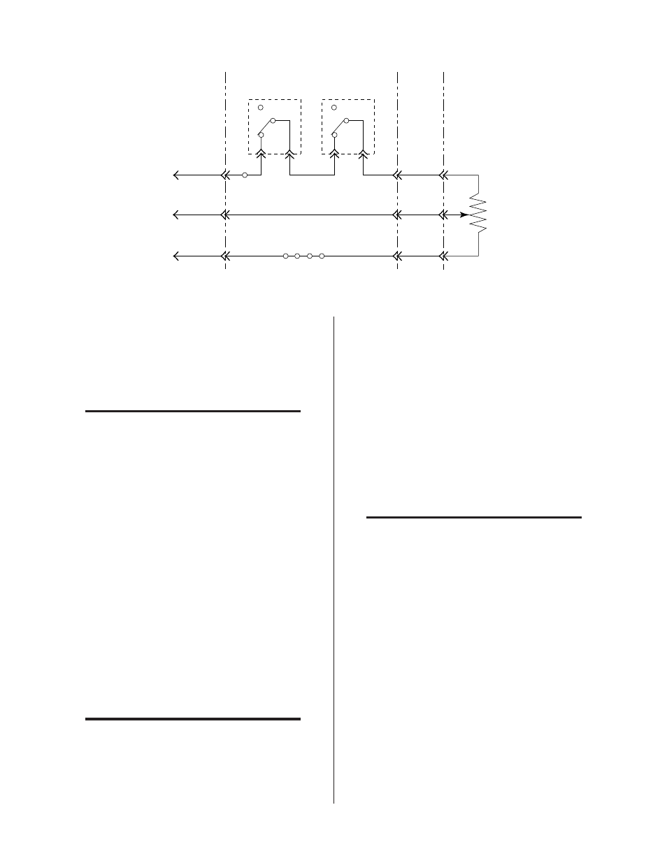
Page 40: C. cp1, cs1 & gs1 pc board removal, Figure 5-3 current control diagram
Section Name
34
Manual 0-2023
5.05 WT1 Weld Timer Parts
Replacement Procedures
NOTE
Refer to Section 6.08 for parts list and overall de-
tail drawing.
A. WT1 Timer Thumbwheel Switch
Replacement
1. Remove WT1 from Weld Sequencer Enclosure by re-
moving the four (4) outside button head screws on
the front panel (see Parts List)
2. Remove the WT1 cover.
3. Remove the four (4) screws that hold the timer switch
to the front panel. Use 3/64" hex wrench for the screw
head and 3/16" driver for the hex nut.
4. To remove the switch, press down on the large PC
board beside the two blue rectangular resistor assem-
blies while pulling up on the switch assembly until it
clears the white connector.
5. Install the new switch by reversing the above steps.
B. WT1 PC Board Replacement
NOTE
Refer to Section 6.08 for parts list and overall de-
tail drawing.
1. Remove the Timer Thumbwheel Switch per Section
5.05-A.
2. Remove the ON/OFF switch knob by pulling straight
out. Remove the hex nut that secures the switch to the
front panel.
3. Remove the two screws securing the front of the PC
board to the two spacers.
4. Press each locking tab of the two plastic PC board sup-
ports inward and slide the PC board off.
5. Install the new PC board by reversing these steps.
C. CP1, CS1 & GS1 PC Board Removal
NOTE
Refer to Sections 6.05, 6.06 and 6.06 for parts list
and overall detail drawing.
1. Remove cover from the module
2. Disconnect the plug from the PC board.
3. Remove all the single knobs from the switches mounted
on the PC board by pulling straight out. Remove all
the concentric (dual) knobs (CS1 only) by loosening
the set screws securing each knob to the switch shaft.
Orange
Console/Power
Supply Control
Cable
Weld Sequencer Enclosure
Remote
Control
Cable
RP1
Red
Blue
J5-1
J5-7
J5-13
ON
OFF
ON
OFF
CS1 or Jumper
CP1 or Jumper
J6-1
J6-7
J6-13
J9-1
J9-7
J9-13
J8-5
J8-6
J7-5
J7-6
TB3-4
20
20
24
11
TB1
1 2 3 4
11
21
23
High
Wiper
Low
23
24
11
Min
Max
Current
Control
(10K ohms)
A-02439
Figure 5-3 Current Control Diagram