D. wt1 weld timer, E. gs1 gas slope, Figure 4-9 adjusting cp1 controls – Tweco Weld Sequencer User Manual
Page 32
OPERATION
26
Manual 0-2023
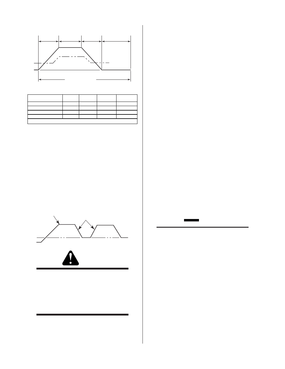
SLOPE
Time
ON Time
(Peak Current)
SLOPE
Time
ON Time
(Background Current)
Peak Current
Background Current
Minimum Current
A-02434
Total Pulse Time
By Increasing
On-Time
(Peak)
Slope Time
On-Time
(Background)
Total Pulse
Time
PULSE RATE
Decreases
Unchanged
Decreases
Decreases
PERCENT ON TIME
Increases
Unchanged
Decreases
Unchanged
PULSE SLOPE
Unchanged
Decreases
Unchanged
Decreases
BACKGROUND CURRENT
Unchanged
Decreases
Unchanged
Decreases *
* = No change when Slope Rate set at MAX
Figure 4-9 Adjusting CP1 Controls
4. Determine necessary background current and calcu-
late the percent of the power supply range setting as
done for CS1 INITIAL CURRENT. If the welding con-
sole has an ammeter, while welding, set by pulling
the BACKGROUND CURRENT knob out and rotate
the knob until the desired amperage is read on the
ammeter. Push the knob back in.
5. While making a sample weld, adjust the PULSE SLOPE
control knob until the desired rate of change between
background and peak current is achieved.
Pe a k C u r r e n t
P u l s e S l o p e
B a ck gr o u n d C u r r e n t
A - 0 2 4 3 5
WARNING
The RP1 Control CONTACTOR ON/OFF switch
must be in the OFF position before the Weld Se-
quencer Enclosure or any control module is shut
OFF. If this is not done and the torch is close
enough to the workpiece (or ground) when the
welding system is energized an arc transfer can
occur.
D. WT1 Weld Timer
WT1 controls weld time from the start of upslope to the
start of the downslope (timed out) sequence when CS1 is
used. Calculate or determine the time by timing the se-
quence during a test weld.
When WT1 is used to time spot welds determine the 'time
on' of the weld. Contactor closure will activate the timer
for each spot weld. Make sure to shut CS1 off when spot
welding.
1. Set the SECONDS-TENTHS dial to the required weld
time.
2. Move the ON/OFF switch to the ON position to acti-
vate the timer.
3. Activate the RP1 CONTACTOR ON switch. One spot
weld sequence will be completed.
4. Press the RP1 SPOTWELD switch as required for ad-
ditional welds.
E. GS1 Gas Slope
1. Make sure plasma gas supply is turned on.
2. Make sure the welding console is in SET mode and
power is ON.
3. Move the GS1 ON/OFF switch to ON position.
4. Move the GS1 MANUAL/AUTO switch to MANUAL
position.
5. Move the GS1 UP/DOWN switch to DOWN position
(momentary)
CAUTION
Minimum sloping and maximum gas flow rates
must stay within the acceptable range of the cur-
rent at each point to prevent tip damage (gas flow
too low) or cutting action (gas flow too high).
6. Adjust the MIN GAS FLOW knob until the required
minimum plasma gas flow rate is shown on the weld-
ing console flowmeter.
7. Move the GS1 UP/DOWN switch to UP position (mo-
mentary).
8. Adjust the MAX GAS FLOW knob until the required
maximum plasma gas flow rate is shown on the weld-
ing console flowmeter.
9. Adjust GS1 UPSLOPE RATE to correspond to current
upslope rate (if CS1 is used) or to achieve the desired
rate refer to Figure 4-10.