Section 4: operation, 01 introduction, 02 functional overview – Tweco Weld Sequencer User Manual
Page 25: 03 weld sequencer enclosure control descriptions, Section 4, Operation, Figure 4-2 weld sequencer enclosure, Wt 1
Manual 0-2023
19
OPERATION
SECTION 4:
OPERATION
4.01 Introduction
This section provides a description of the Power Supply
operating controls and procedures. Identification of the
Front and Rear Panel components is followed by operat-
ing procedures.
4.02 Functional Overview
The Weld Sequencer is designed to automatically control
the output of most solid-state power supplies. The Weld
Sequencer gives the operator more accurate control of the
variables within a welding operation. Once the Weld Se-
quencer is programmed for a particular welding opera-
tion, the weld can be reproduced with minimal fluctua-
tions. Four separate solid-state control modules, a Weld
Sequencer Enclosure and a RP1 Control remote pendant
make up the Weld Sequencer. Any combination of the
four modules can be used with the Weld Sequencer En-
closure to be a stand-alone unit.
CP1
PULSER
CS1
CURRENT SLOPE
GS1
GAS SLOPE
WT 1
WELD TIMER
T E N T H S
S E C O N D S
O N
O F F
O N
AC P OW E R
O F F
M I N
G A S F L OW
. 5 - 3 S C F H
. 2 5 - 1 . 4 l p m
M A X
G A S F L OW
2 - 7 S C F H
1 - 3 . 3 l p m
0
1
2
3
4
5
6
7
8
9
1 0
0
1
2
3
4
5
6
7
8
9
1 0
U P S L O P E
R AT E
0
1
2
3
4
5
6
7
8
9
1 0
D OW N S L O P E
R AT E
0
1
2
3
4
5
6
7
8
9
1 0
D OW N S L O P E
D E L AY
( 0 - 1 0 s e c . )
0
1
2
3
4
5
6
7
8
9
1 0
A - 0 2 4 1 4
O N
O F F
O N
O F F
I N I T I A L
0
1
2
3
4
5
6
7
8
9
1 0
C U R R E N T T I M E
0
1
2
3
4
5
6
7
8
9
1 0
U P S L O P E R AT E
D OW N S L O P E
0
1
2
3
4
5
6
7
8
9
1 0
D E L AY R AT E
F I N A L
0
1
2
3
4
5
6
7
8
9
1 0
C U R R E N T T I M E
0 - 10 sec.
0 - 10 sec.
weld time
0 - 10 sec.
G A S F L OW
M I N
S L O P I N G
M A X
U P
D OW N
M A N UA L
AU TO
O N
O F F
0
1
2
3
4
5
6
7
8
9
1 0
P U L S E R AT E
0
1
2
3
4
5
6
7
8
9
1 0
P E R C E N T O N T I M E
0
1
2
3
4
5
6
7
8
9
1 0
P U L S E S L O P E
0
1
2
3
4
5
6
7
8
9
1 0
BAC K G RO U N D C U R R E N T
( p u l l fo r d i s p l ay )
Figure 4-1 Control Modules Assembled In Weld
Sequencer Enclosure
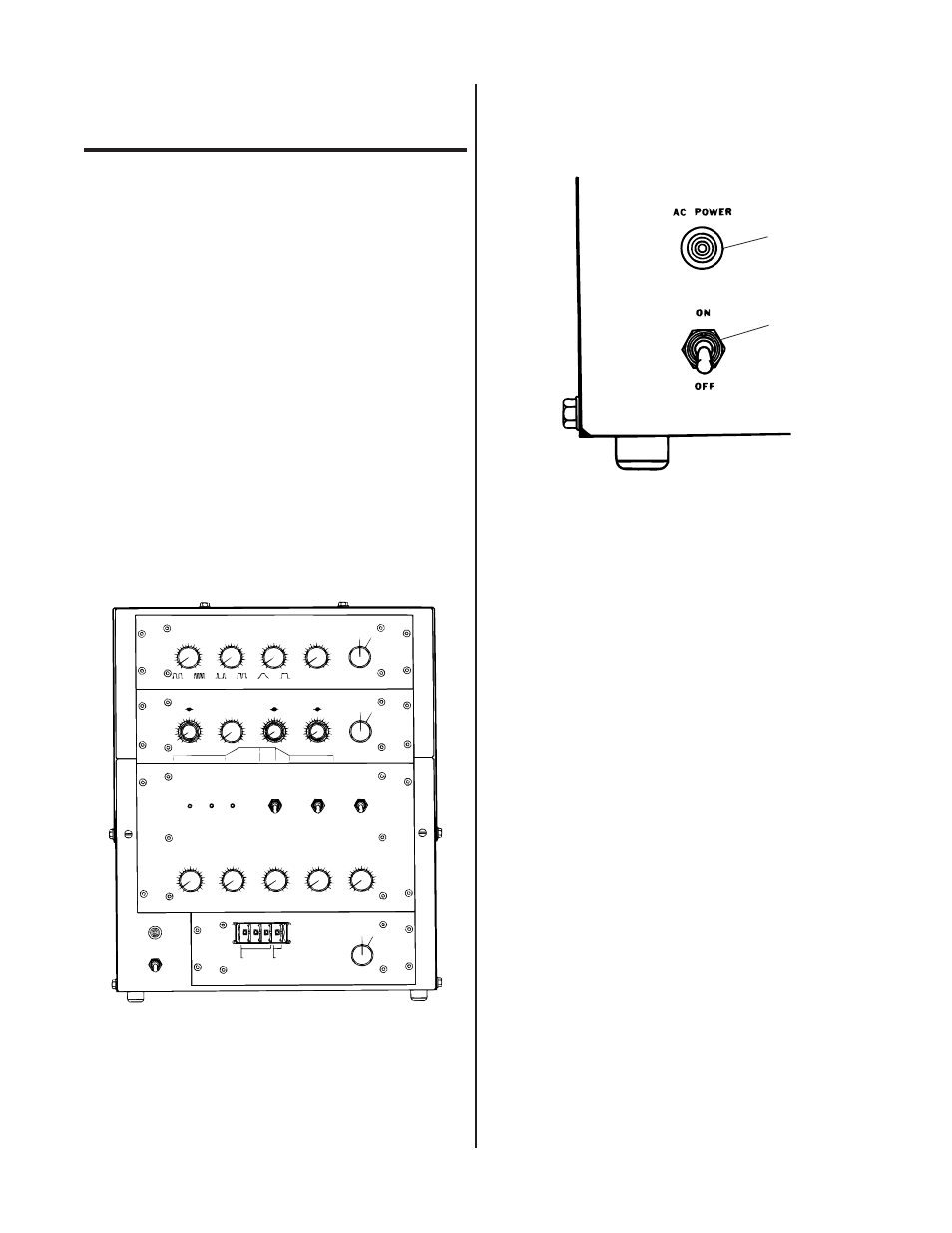
4.03 Weld Sequencer Enclosure
Control Descriptions
A - 0 2 4 1 5
1
2
Figure 4-2 Weld Sequencer Enclosure
1. ON/OFF Switch
Activates Weld Sequencer Enclosure power circuits
and supplies AC power to all Sequencer Controls in
ON position. In the OFF position deactivates all Se-
quencer Control circuits.
2. Red AC Power Light
Indicates that AC power is being supplied to the Se-
quencer control modules.