05 wt1 weld timer – Tweco Weld Sequencer User Manual
Page 19
Manual 0-2023
13
INSTALLATION PROCEDURES
2. Connect the mating plug of the 10 foot (3 m) Control
Cable to the receptacle on the rear panel of the Weld
Sequencer Enclosure marked CONSOLE/POWER
SUPPLY CONTROL.
3. The connection on the other end of the cable depends
on the welding console, power supply or current con-
trol device. Connect as follows (refer to Figure 3-4):
• Thermal Arc WC100B Welding Console
a. Connect Control Cable plug to the receptacle on
the front panel of the WC100B marked REMOTE
CONTROL. Move REMOTE ON/OFF switch to
ON position.
• Thermal Arc WC100A and WC122A (and earlier
models) Welding Consoles
b. Cut the Control Cable plug off and strip cable jacket
back approximately 2 inches.
c. Locate the cable from the welding console CON-
TROL receptacle. Measure enough cable to con-
nect with the Control Cable from the Weld Se-
quencer Enclosure and cut.
d. Connect the white/brown (J5-3) and black (J5-4)
wires of the Weld Sequencer Enclosure Control
Cable to the two leads of the cable from the weld-
ing console CONTROL. The order of connection
is unimportant. This connection gives contactor
control to the Sequencer.
e. Connect a cable to the Remote Amperage Control
of the power supply. Connect the other end to the
Weld Sequencer Enclosure Control Cable (see Fig-
ure 3-E):
Power Supply Amperage Control maximum lead
to orange wire (J5-1)
Power Supply Amperage Control variable (wiper)
lead to red wire (J5-7)
Power Supply Amperage Control minimum lead
to blue wire (J5-13)
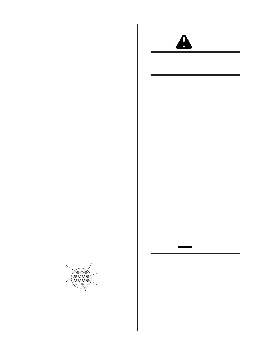
C o n t a c t o r
C o n t r o l
A M P C o n t r o l
( W i p e r )
A M P C o n t r o l
( M i n )
A M P C o n t r o l
( M a x )
C o n t a c t o r
C o n t r o l
G r o u n d
1
4
8
1 3
7
3
A - 0 2 4 0 8
Figure 3-5 Back View of Control Cable Plug
f. Tape back the wires not used.
• Other Welding Consoles and Power Supplies
WARNING
The remote control circuit of the welding console
or power supply must not exceed 28 volts AC or
DC.
a. Cut the cable plug off. Strip the cable jacket back
approximately 2 inches.
b. Connect the white/brown (J5-3) and black (J5-4)
wires of the Weld Sequencer Enclosure Control
Cable to the contactor control of the welding unit.
This gives contactor control to the Sequencer.
c. Connect a cable to the Remote Amperage Control
of the power supply. Connect the other end to the
Weld Sequencer Enclosure Control Cable (refer to
Figure 3-5):
Power Supply Amperage Control maximum lead
to orange wire (J5-1)
Power Supply Amperage Control variable (wiper)
lead to red wire (J5-7)
Power Supply Amperage Control minimum lead
to blue wire (J5-13)
d. Tape back the wires not used.
e. Check input power connections on the terminal
strip TB4, located on the rear panel of the Weld
Sequencer Enclosure, to be sure that they are set
up for the available voltage. Provisions are made
for primary inputs of 115 or 230 volts AC (refer to
Section 4.2) and 50 or 60 Hz power may be used.
3.05 WT1 Weld Timer
CAUTION
The WT1 Weld Timer is factory set for 60 Hz op-
eration. If 50 Hz power is used or WT1 doesn’t
time properly remove the cover from WT1 and check
the position of the switch mounted in the middle of
the PC board. Move the handle to the proper posi-
tion printed on the PC board (50 or 60).
1. Install WT1 into the bottom of the opening in the Weld
Sequencer Enclosure (refer to Figure 3-6). Secure with
screws provided.
2. Connect WT1 to the Weld Sequencer Enclosure wiring
harness with the J4 connectors.