Section 3: installation procedures, 01 introduction, 02 site selection – Tweco Weld Sequencer User Manual
Page 17: 03 unpacking, 04 equipment installation - general, Section 3, Installation procedures
Manual 0-2023
11
INSTALLATION PROCEDURES
SECTION 3:
INSTALLATION
PROCEDURES
3.01 Introduction
This section describes installation of the Weld Sequencer.
These instructions apply to the Weld Sequencer only; in-
stallation procedures for the Power Supply, Welding Con-
sole, Torch, Options, and Accessories are given in Manu-
als specifically provided for those units.
The complete installation consists of:
1. Site selection
2. Unpacking
3. Connections to Weld Sequencer
4. Operator training
3.02 Site Selection
The Weld Sequencer Enclosure should be located either
next to or on top of the Welding Console (GS1 connec-
tions must be installed in Welding Console before mount-
ing on top). A source of 115 or 230 VAC power must also
be available.
NOTE
Review Important Safety Precautions (page 1) to
be sure that the selected location meets all safety
requirements.
3.03 Unpacking
Each component of the system is packaged and protected
with a carton and packing material to prevent damage
during shipping.
1. Unpack each item and remove all packing material.
2. Locate the packing list(s) and use the list to identify
and account for each item.
3. Inspect each item for possible shipping damage. If
damage is evident, contact your distributor and/or
shipping company before proceeding with system
installation.
3.04 Equipment Installation -
General
WARNING
Make sure that all power to the welding system is
shut off at the incoming source. Do not turn ON
the power until all components are connected.
A. Voltage Selection
The Weld Sequencer Enclosure is factory-wired for 230V,
60Hz operation. If 230V primary power is available, con-
nect the end of the input power cord to the 230V primary
power source.
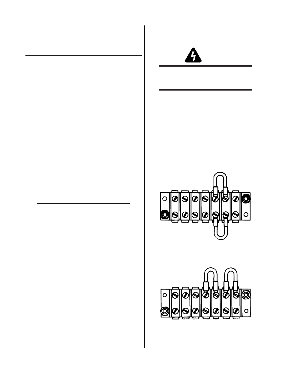
If 115V primary power is to be used change TB4 connec-
tions as follows:
1. Locate TB4 terminal strip on the rear panel of the En-
closure. Remove the two jumpers from each side of
terminals 5 and 6.
230 Volt Jumpers
TB4 Terminal Strip
A-02404
1 2 3 4 5 6 7
Figure 3-1 Jumper Installation For 230 VAC Input
2. Connect one jumper across terminals 4 and 5 and the
other across 6 and 7.
115 Volt Jumpers
TB4 Terminal Strip
A-02405
1 2 3 4 5 6 7
Figure 3-2 Jumper Installation For 115 VAC Input