E-flite AT-6 Texan 25 ARF User Manual
Page 34
34
E-flite AT-6 Texan ARF Assembly Manual
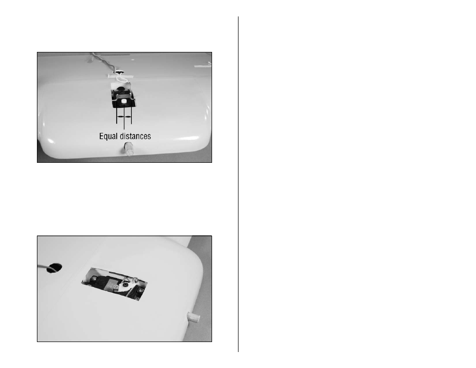
14. Check that both linkages are an equal distance from
the output of the retract servo. Adjust the linkages as
necessary.
15. Install a servo arm that aligns with the position of the
linkages when installed. Secure the horn using the screw
from the servo. The position of the linkages will be fine-
tuned in the following step. Secure the wires using two
1/16-inch wheel collars to the top of the servo pushrods
to work as keepers.
Servo travel is important when installing retracts.
16. Check the operation of the retracts using the radio
system at this time, without the wheels installed. Too
much travel can create binding, resulting in a retract
mechanism that will not operate, cause excessive loads
on the retract servo, and possibly drain the flight battery
prematurely. Too little travel will result in a retract that will
not lock in the up or down positions. Test the operation
of the gear and locking mechanism by cycling the gear
using the radio system. Simulate a load on the locking
mechanism by pushing or pulling on the wire strut in
both the up and down positions. If the gear does not
lock, or becomes unlocked during the testing, the travel
at the servo must be adjusted either mechanically or at
the radio system using the endpoint adjustments of the
retract channel. Readjust as necessary and re-check
the operation until the retracts lock in both the up and
down positions and that the servo is not stalled in either
position as well. Take your time to get the operation of
the retracts correct before continuing.