Aileron servo installation – E-flite AT-6 Texan 25 ARF User Manual
Page 20
20
E-flite AT-6 Texan ARF Assembly Manual
Aileron Servo Installation
Required Parts
Outer wing panels (right and left)
Servo w/hardware (2)
3mm x 10mm self-tapping screw (8) Clevis retainer (2)
2
1
/
2
-inch (64mm) pushrod wire
Clevis (2)
Pushrod connector (2)
6-inch (152mm) servo extension (2)
Servo mounting block
3/4 x 3/8 x 3/8-inch (19 x 9.5 x 9.5mm) (4)
Required Tools and Adhesives
Drill
Drill bit: 1/16-inch (1.5mm)
6-minute epoxy
Pencil
Phillips screwdriver: #1
Felt-tipped pen
Side cutters
Pliers
Thin CA
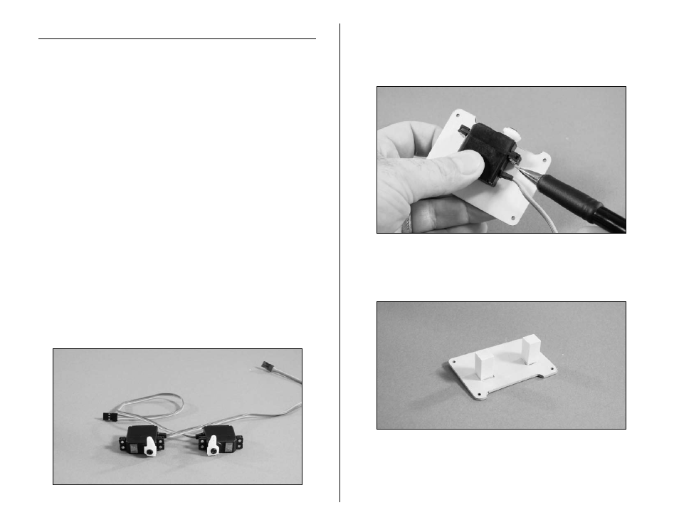
1. Plug the aileron servos into the radio system and make
sure they operate and are centered as well.
2. Prepare the aileron servos for installation by removing
any unnecessary arms from the servo horns as shown
using side cutters. Install any grommets and brass
eyelets at this time as well. The servos will have the arms
installed opposite of each other as shown in the photo.
3. Position the aileron servo on the servo cover so the
arm is centered lengthwise in the cutout. The arm will
align with the edge of the servo cover as well. Use a
pencil to mark the position of the servo on the cover.
4. Use 6-minute epoxy to glue the servo mounting block
to the servo cover as shown. Allow the epoxy to fully cure
before proceeding.
Note: You will find the servo mounting blocks in your
kit to vary in length from the measurements listed
above. They have been cut to the correct length from
the manufacturer.