E-flite AT-6 Texan 25 ARF User Manual
Page 26
26
E-flite AT-6 Texan ARF Assembly Manual
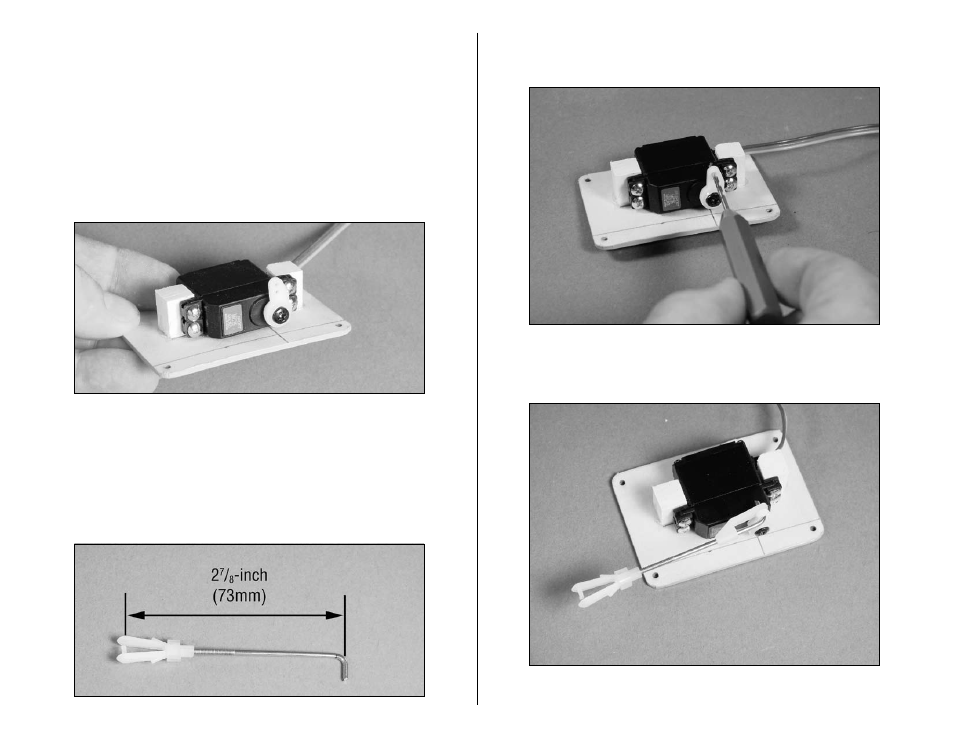
6. Position the servo between the servo mounting blocks.
Use a pencil to mark the locations for the servo mounting
screws on the blocks. The servo should not touch the
cover to prevent it from absorbing vibrations from the
airframe. Use a drill and 1/16-inch (1.5mm) drill bit to
drill the holes for the servo mounting screws. Apply a
few drops of thin CA to each of the holes to harden the
surrounding wood. Use a #1 Phillips screwdriver to install
the screws provided with the servo to attach it to the
servo mounting blocks.
7. Slide a clevis retainer onto a nylon clevis. Thread the
clevis onto one of the 2
7
/
8
-inch (73mm) pushrod wires.
Measure back 2
7
/
8
-inch (73mm) from the pin in the clevis
and mark the pushrod wire. Make a 90-degree bend at
the mark. This will give you a good starting length for the
installation of the flap linkage.
8. Use a pin drill and 5/64-inch (2mm) drill bit to
enlarge the outer hole in the servo arm.
9. Attach the pushrod to the flap servo using a pushrod
connector.