Fixed landing gear installation – E-flite AT-6 Texan 25 ARF User Manual
Page 28
28
E-flite AT-6 Texan ARF Assembly Manual
Fixed Landing Gear Installation
Required Parts
Wing center section
Landing gear (right and left)
1/8-inch wheel collar (4)
3mm x 4mm machine screw (2)
3mm x 10mm self-tapping screw (8)
Required Tools and Adhesives
Drill
Drill bit: 5/64-inch (2mm)
Thin CA
File
Phillips screwdriver: #1, #2
Pencil
Threadlock
Note: The main wire struts included with your kit have
been upgraded from the preproduction versions shown
in this manual. Please note your wire struts will have the
main wire yoke offset as per the real AT-6 landing gear.
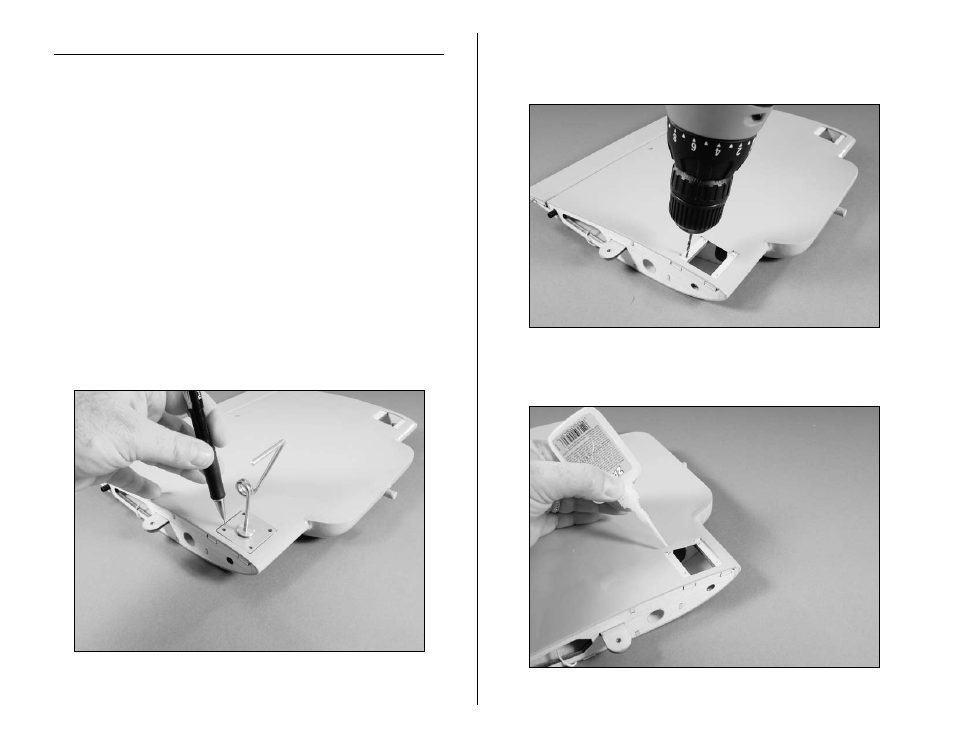
1. Position the main gear on the rails of the wing center
section. Use a pencil to transfer the locations for the four
mounting screws through the gear and onto the rails.
2. Use a drill and 5/64-inch (2mm) drill bit to drill the
four holes for the mounting screws. Use care not to
accidentally drill through the top of the wing.
3. Apply a few drops of thin CA to each of the holes to
harden the surrounding wood.
- Habu 32x DF ARF (84 pages)
- A6M5 Zero 300 BNF Basic (17 pages)
- Hawker Sea Fury 480 ARF (28 pages)
- Mystique RES 2.9m ARF (52 pages)
- Super Cub 25e ARF (48 pages)
- LR-1A Pogo ARF 15e (21 pages)
- J-3 Cub 450 (40 pages)
- Hawker Hurricane 25e PNP (26 pages)
- Hawker Hurricane 25e PNP addendum (1 page)
- Apprentice 15e PNP (28 pages)
- Sukhoi SU-26m 480 ARF (28 pages)
- Beechcraft Bonanza 15e ARF (60 pages)
- Byp Yak 3D ARF (40 pages)
- Ultimate Fx 3D ARF (40 pages)
- Tribute FX 3D ARF (28 pages)
- Sobre 3D Profile (32 pages)
- Ascent EP Park Glider ARF (23 pages)
- Float Set Complete: Carbon-Z Cub (2 pages)
- Carbon-Z Cub PNP (27 pages)
- Carbon-Z Cub PNP Addendum (1 page)
- BAe Hawk 15 DF ARF (36 pages)
- Edge 540QQ 280 BNF Basic (19 pages)
- P-40 Warhawk 300 ARF (20 pages)
- Hawker Sea Fury 400 ARF (40 pages)
- Clipped Wing Cub 250 ARF (40 pages)
- T-34 Mentor 25e ARF (28 pages)
- Ultra Stick 25e ARF (40 pages)
- Ultra Stick 25e ARF Programming Guide (5 pages)
- Slick 3D 480 ARF (48 pages)
- PT-19 450 ARF (44 pages)
- Extra 330SC BP 3D ARF (40 pages)
- Cap 232 BP ARF (44 pages)
- Brio 10 ARF (56 pages)
- Park 480 BL Motor Combo (4 pages)
- Mini Edge 3D ARF (44 pages)
- Cessna 182 370 ARF (32 pages)
- Cessna 182/Park 400 BL Motor Combo (4 pages)
- Tribute 3D Profile ARF (40 pages)
- Fokker DVII 250 ARF (28 pages)
- Enticement F3P ARF (36 pages)
- Carbon-Z Yak 54 3X BNF Basic (23 pages)
- Carbon-Z Scimitar PNP (28 pages)
- UMX B-17G Flying Fortress BNF (18 pages)
- UMX Sbach 342 3D BNF Basic (17 pages)