Retractable landing gear installation – E-flite AT-6 Texan 25 ARF User Manual
Page 30
30
E-flite AT-6 Texan ARF Assembly Manual
7. Slide the wheel onto the landing gear wire, then a
final wheel collar. Use a 3mm x 4mm machine screw and
#1 Phillips screwdriver to secure the wheel collar. Use
threadlock on the screw to prevent it from vibrating loose.
8. Repeat Steps 1 through 7 for the remaining landing
gear and wheel.
Retractable Landing Gear Installation
Required Parts
Wing center section
Retract servo w/hardware
Retracts w/hardware
Retract linkage (2)
Nylon clevis (2)
Clevis retainer (2)
Required Tools and Adhesives
Thin CA
Pencil or felt-tipped pen
Covering iron
Hobby knife
Drill
File
Phillips screwdriver: #1
Threadlock
1/16-inch wheenl collar w/setscrew (2)
Drill bit: 1/16-inch (1.5mm), 5/64-inch (2mm)
Optional Parts
Robart 2
1
/
2
-inch (63mm) wheels
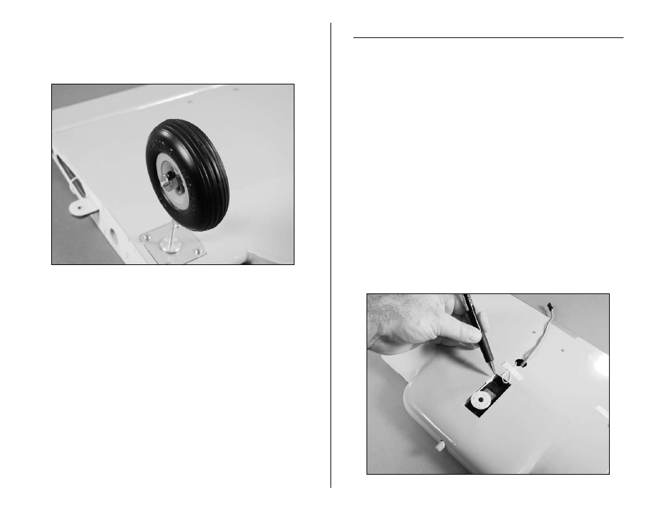
1. Position the retract servo in the opening, guiding
the servo lead under the servo mounting rail at the
rear and out the hole in the wing center section. Mark
the location of the servo mounting screws using a pencil
or felt-tipped pen.