Main radio installation – E-flite AT-6 Texan 25 ARF User Manual
Page 16
16
E-flite AT-6 Texan ARF Assembly Manual
Main Radio Installation
Required Parts
Fuselage
Receiver
Servo w/hardware (3)
Pushrod connector (3)
Hook and loop material
Required Tools and Adhesives
Thin CA
Felt-tipped pen
Side cutters
Pliers
Pin drill
Phillips screwdriver: #1
Drill bit: 1/16-inch (1.5mm), 5/64-inch (2mm)
Note: The installation of the elevator servos will require
either of the following options, as using a standard
Y-harness for the servos will result in the servos moving
the control surfaces in the opposite directions.
Option 1: Use a computer radio to mix the elevator
servos together using two separate channels. Ensure you
use a correct mix in your radio that has an active trim to
trim both elevators in flight.
Option 2: Use a reversing Y-harness (EXRA320) between
the two servos and the receiver.
1. Turn on your radio system and select a new model if
using a computer radio. Make sure all the sub trims have
been set to 0 and no mixing functions are turned on.
Center the trim levers and stick at this time as well. Plug
the servos into the radio system and make sure all servos
operate and are centered as well.
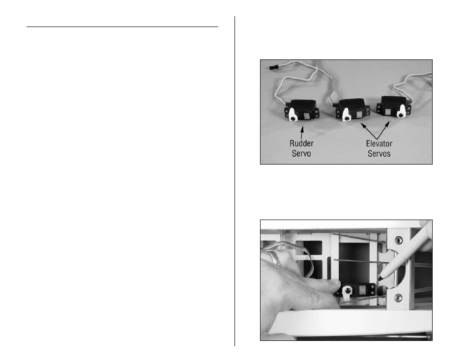
2. Prepare the rudder and elevator servos for installation
by removing any unnecessary arms from the servo horns
as shown using side cutters. Install any grommets and
brass eyelets at this time as well.
3. Position the elevator servo in the fuselage, aligning the
outer hole in the servo arm with the elevator pushrod.
Mark the locations for the servo mounting screws on the
servo mounting rails using a felt-tipped pen.