Diode LED K-RANGE 24 Wall Mount Controller User Manual
Page 2
INSTALLATION GUIDE
K-RANGE 24™ WALL MOUNT CONTROLLER
2 of 2
IG022614-1.0
Fixture does not illuminate
• Ensure the system is wired correctly.
• Verify polarities are correct.
• Ensure a compatible constant voltage dimmable fixture is installed.
• Ensure a compatible constant voltage driver is installed.
• Ensure the driver and fixture have the same voltage specifications (12V & 12V, or 24V & 24V).
Fixture is flashing or flickering
• Verify a compatible constant voltage driver is installed.
• Ensure a compatible constant voltage dimmable fixture is installed.
• Ensure all connections are properly secured.
• Ensure no more than a single controller is attached to each driver output.
Fixture is slowly flashing
• Ensure driver is not overloaded. An overloaded driver will cause the internal auto-reset of the driver
to trip repeatedly.
Correct colors are not illuminating
• Verify the correct leads are connected to the correct terminals on the receiver. Some tape light MFG
labeling varies. Swap WW and CW leads if necessary.
• Ensure potential leads at opposing end of fixture are not crossed.
Touchpad does not respond
• Ensure the ribbon cable inside the faceplate is properly secured.
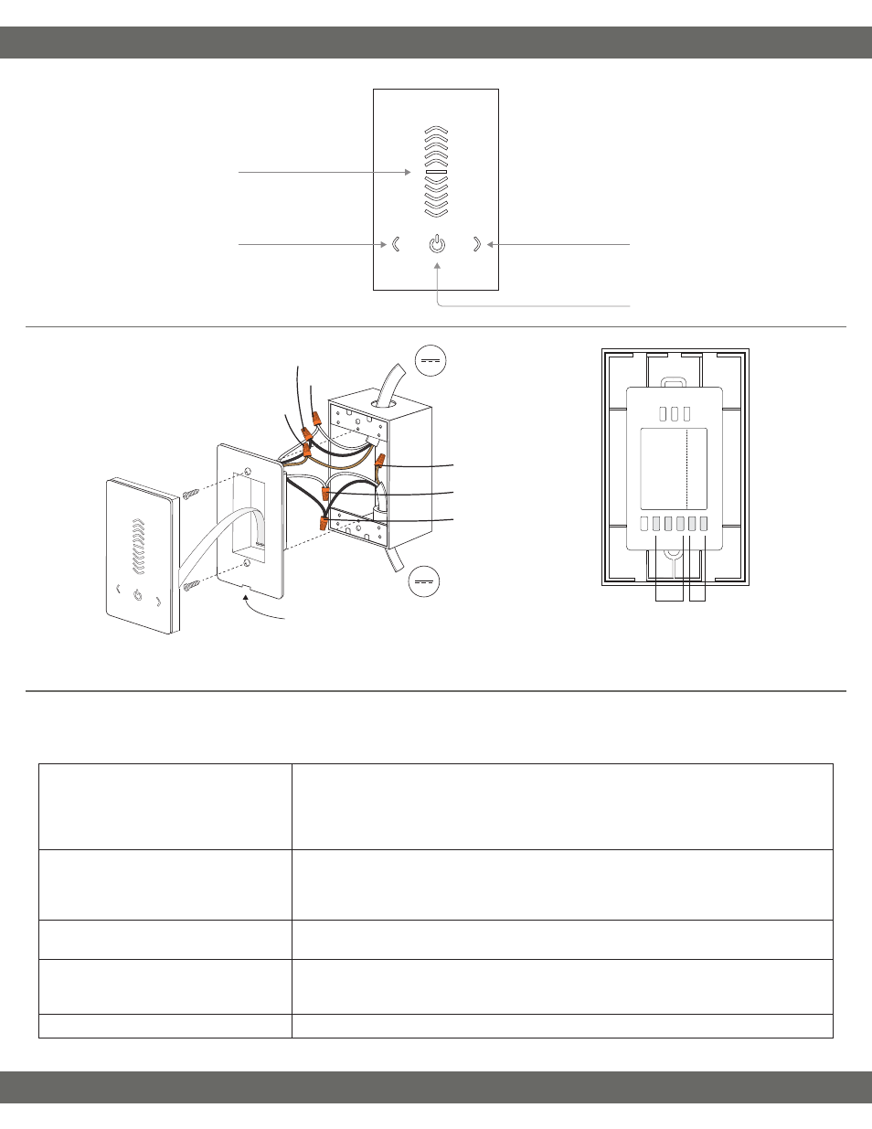
Operation
Mounting & Wiring Connections
Troubleshooting
Prior to troubleshooting, ensure a compatible system is installed. Verify compatible fixtures, drivers, controls and additional components were specified
correctly. For additional questions/concerns, contact technical support. Please have all part numbers on hand for fast and efficient technical assistance.
From 12-24VDC
LED Driver
To 12-24VDC
LED Load
V− (from driver)
V+ (from driver)
Extra wire (cap off)
WW (to fixture)
V+ (to fixture)
CW (to fixture)
Pop off faceplate with a flathead screwdriver.
Kelvin Adjustment
Adjust Kelvin (color temperature)
Decrease Brightness
Decrease brightness (80 levels)
Increase Brightness
Increase brightness (80 levels)
Power/Sound
Turn controller On/Off. Hold for
3 seconds to turn sound On/Off.
WW CW V+ V+ V−
From 12-24VDC
LED Driver
To 12-24VDC
LED Load
Determine the number of low voltage outputs of the driver when installing multiple PWM controllers. No more than one PWM controller can be attached to
a single output of the driver.