System diagrams, Mlv dimmer diagram 3-way mlv dimmer diagram – Diode LED Magnetic Dimmable Driver 12V & 24V User Manual
Page 2
Page 2 of 3
MAGNETIC DIMMABLE DRIVER
INSTALLATION GUIDE
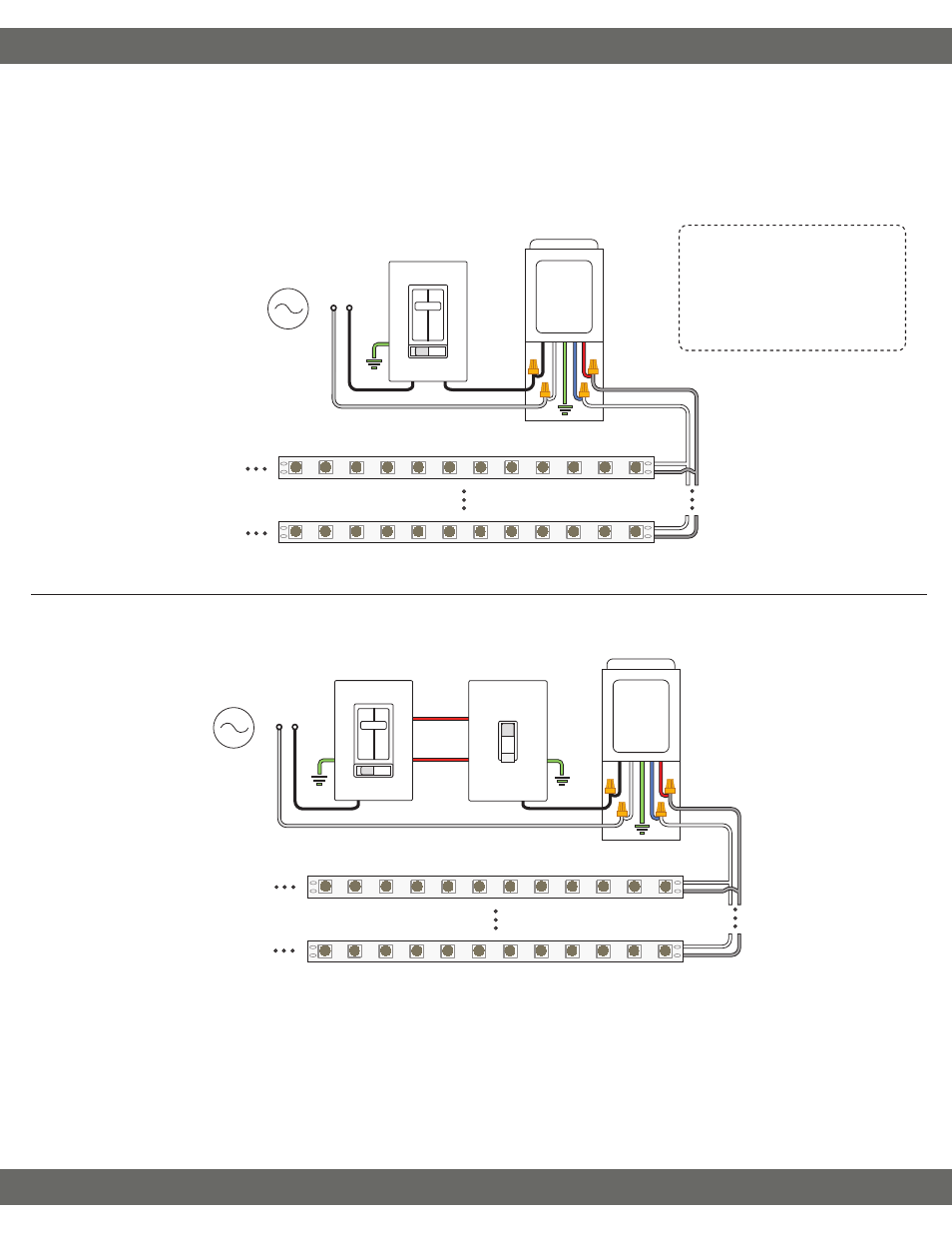
System Diagrams
The following diagrams are provided as example system designs. Use the Orange Boost Tap (see ‘Boost Tap’) as an optional voltage boost in place
of the Black (Line) wire if the fixture is receiving noticeable light degradation (200W & 300W models only). Cap the existing hot wire not in use. See
‘Boost Tap’ on previous page. Install in accordance with the NEC and local regulations.
L = Line (Black)
N = Neutral (White)
GND = Ground (Green)
V+ = Low Voltage Positive
V- = Low Voltage Negative
MLV Dimmer Diagram
3-Way MLV Dimmer Diagram
† Install a compatible magnetic low voltage dimmer switch. See dimmer switch manufacturer installation guide for complete wiring instructions.
†† Dimmable drivers require a compatible magnetic low voltage dimmer switch to supply the driver and fixture with appropriate input voltage.
Do not test or install directly connected to an AC power source or On/Off switch. It is recommended to load the driver no more than 80% its
labeled rating for maximum longevity. See dimmer switch manufacturer specifications for minimum load recommendations.
‡‡ See fixture specifications for maximum series run limits.
AC Power
50/60Hz
120VAC Magnetic Low
Voltage Dimmer†
V+ (Red)
V- (Blue)
LED Strip Light / Fixture‡‡
L
N
N (White)
L (Black)
Magnetic
Dimmable Driver††
Install applicable wire gauge / type
V+
V-
V+
V-
GND (Green)
AC Power
50/60Hz
Traveling
Lines
3-Way On/Off Switch
120VAC Magnetic Low
Voltage Dimmer†
Magnetic
Dimmable Driver††
V+ (Red)
V- (Blue)
N (White)
L (Black)
V+
V-
V+
V-
Install applicable wire gauge / type
LED Strip Light / Fixture‡‡
L
N
GND (Green)