Rockwell Automation DeviceLogix System User Manual User Manual
Page 189
Publication RA-UM003B-EN-P - February 2010
189
RSNetWorx for DeviceNet Software and the DeviceLogix Editors Appendix B
To change a produced I/O assembly:
1. Click the current value of the Produced I/O Assembly.
The field turns into a drop-down list box.
2. Click the arrow to display the values.
3. Click the desired value.
4. Click Apply to save the new value without closing the window.
Or click OK to save the new value and to close the window.
For the layout of the Produced I/O Assembly for your chosen device,
refer to the Technical Data publication for that device.
IMPORTANT
Apply and download will be unsuccessful unless local logic is
disabled and the device is removed from the scanlist as
discussed in the Download To a Device section.
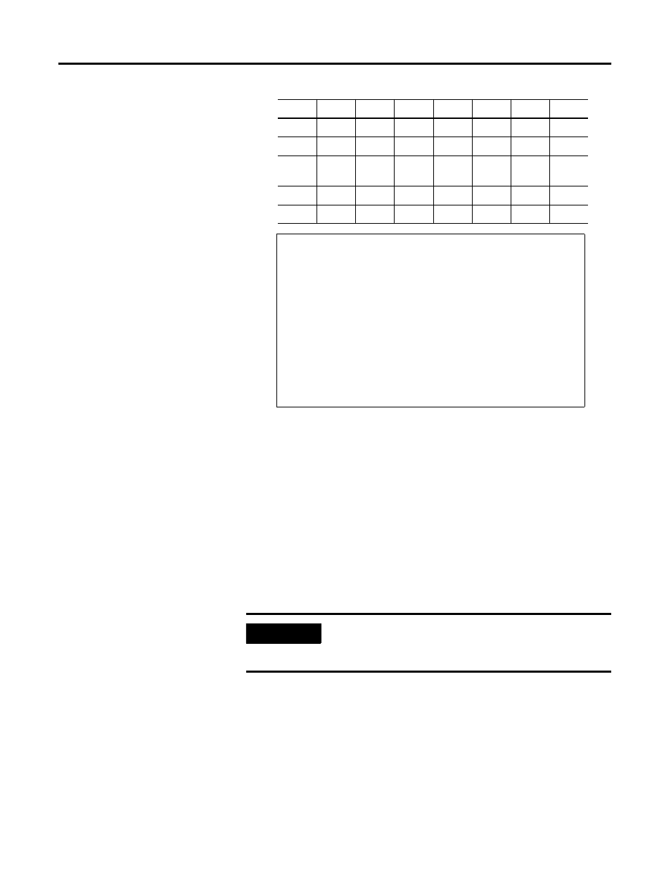
Input 7 Input 6 Input 5 Input 4 Input 3 Input 2 Input 1 Input 0
OW-D
OW-C
OW-B
OW-A
ISC-D
ISC-C
ISC-B
ISC-A
OFLT 7
OFLT 6
OFLT 5
OFLT 4
OFLT 3
OFLT 2
OFLT 1
OFLT 0
OPWR
Logic
Ena
OUT 7
OUT 6
OUT 5
OUT 4
OUT 3
OUT 2
OUT 1
OUT 0
PNB 7
PNB 6
PNB 5
PNB 4
PNB 3
PNB 2
PNB 1
PNB 0
Standard MaXum Status and Diagnostic Bits
OW = Off-Wire; ISC = Input Short Circuit; OFLT = Output Fault; OPWR = Output Power
DeviceLogix Bits;
Logic Ena = DeviceLogix is Enabled. This can be used in the PLC to recognize that the
remote device is running a control program.
Out X = Status of Local Output Bit if it is under control of DeviceLogix
PNB X = Network Output Bits
(Where X = the number of the Output Bit or Network Output Bit.)