Rockwell Automation DeviceLogix System User Manual User Manual
Page 185
Publication RA-UM003B-EN-P - February 2010
185
RSNetWorx for DeviceNet Software and the DeviceLogix Editors Appendix B
Understand Produced Network I/O
(also known as Network Outputs)
Under normal conditions, an I/O device produces the state of its
inputs and the status of any fault information on the device. However
with local logic running on a device, a master controller sometimes
needs to know the results of some intermediate state or value of logic.
Using a special I/O assembly containing network outputs, it is
possible for the device to report the state of any portion of the logic.
Each network output has a space reserved for it in the module’s
produced I/O assembly. When you connect this network output to
something in the logic, those results are reported in the produced
data.
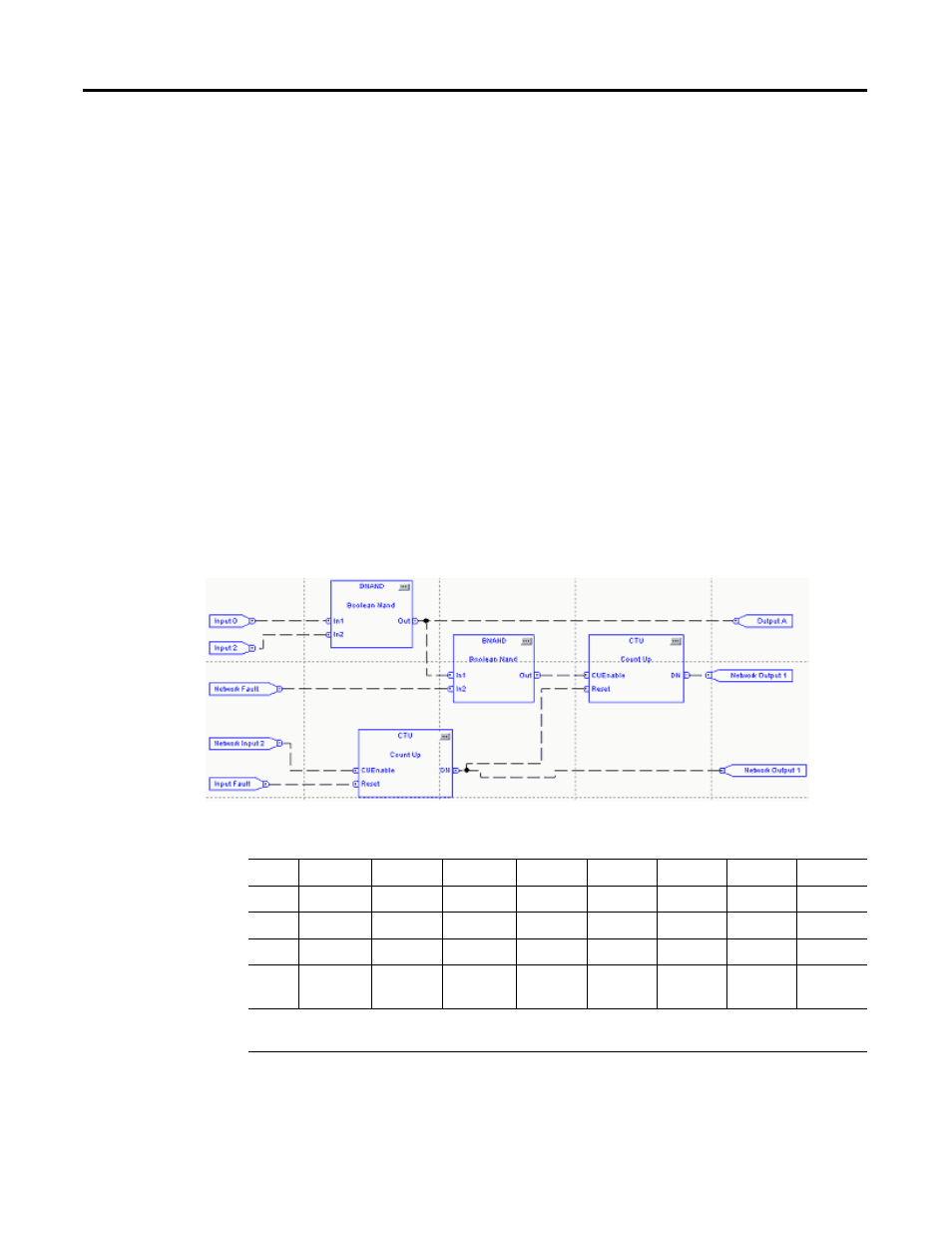
In the following example, you can see when hardware inputs 0 and 1
are on at the same time. This is reported in Network Output 0.
Network Output 1 reports when Faults have occurred. Both of these
pieces of information are reported in the produced I/O data shown
below the example.
Produced I/O Data
Bit 7
Bit 6
Bit 5
Bit 4
Bit 3
Bit 2
Bit 1
Bit 0
Byte 0
In 7
In 6
In 5
In 4
In 3
In 2
In 1
In 0
Byte 1
OPWR
Logic Ena
Byte 2
Out 7
Out 6
Out 5
Out 4
Out 3
Out 2
Out 1
Out 0
Byte 3
Network
Output 7
Network
Output 6
Network
Output 5
Network
Output 4
Network
Output 3
Network
Output 2
Network
Output 1
Network
Output 0
All data in the assembly including Network Outputs are capable of causing a Change of State production.
OPWR = Output Power; Logic Enabled = DeviceLogix Enabled