3 i/o wiring examples – Rockwell Automation SP600 AC Drive User Manual Version 1.0 User Manual
Page 87
Installing Control Wiring
7-5
7.3
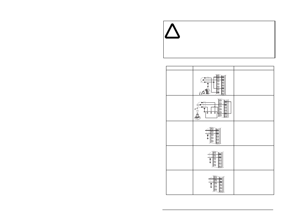
I/O Wiring Examples
!
ATTENTION: Configuring an analog input for 0-20 mA
operation and driving it from a voltage source could cause
component damage. Verify proper configuration prior to
applying input signals.
ATTENTION: Hazard of personal injury or equipment damage
exists when using bipolar input sources. Noise and drift in
sensitive input circuits can cause unpredictable changes in
motor speed and direction. Use speed command parameters
to help reduce input source sensitivity.
Table 7.2 – I/O Wiring Examples
Input/Output
Connection Example
Required Parameter Settings
Potentiometer
Unipolar Speed
Reference
10k Ohm Pot.
Recommended
(2k Ohm minimum)
Select Speed Reference source:
Param. 090 = 1 “Analog In 1”
Adjust Scaling:
Param. 091, 092, 322, 323
Check Results:
Param. 016
Joystick Bipolar
Speed Reference
±10V Input
Set Direction Mode:
Param. 190 = 1 “Bipolar”
Adjust Scaling:
Param. 091, 092, 325, 326
Check Results:
Param. 017
Analog Input Bipolar
Speed Reference
±10V Input
Adjust Scaling:
Param. 091, 092, 325, 326
Check Results:
Param. 017
Analog Input Unipolar
Speed Reference
0 to +10V Input
Adjust Scaling:
Param. 091, 092, 325, 326
Check Results:
Param. 017
Analog Input Unipolar
Speed Reference
4-20 mA Input
Configure Input for Current:
Param. 320, Bit #2 = 1 “Current”
Adjust Scaling:
Param. 091, 092, 325, 326
Check Results:
Param. 017
14
15
22
10
Analog Input 1
18
19
22
Com
Power Source
-10V
+10V
Analog Input 2
18
19
–
+
Analog Input 2
18
19
Common
+
Analog Input 2
20
21
Common
+
Analog Input 2