Rockwell Automation SP600 AC Drive User Manual Version 1.0 User Manual
Page 227
Parameter Descriptions
12-97
23 = Input 3 Link: Outputs the state of digital input 3.
24 = Input 4 Link: Outputs the state of digital input 4.
25 = Input 5 Link: Outputs the state of digital input 5.
26 = Input 6 Link: Outputs the state of digital input 6.
27 = TB in Manual: Terminal block has manual reference control.
Sets the relay activation level for options 10-15 in parameter 380
(Digital Out1 Sel). Units are assumed to match the selection of
parameter 380. (i.e., At Freq = Hz, At Torque = Amps).
Sets the on delay time for the digital outputs. This is the time
between the occurrence of a condition and activation of the relay.
Sets the off delay time for the digital outputs. This is the time
between the disappearance of a condition and de-activation of the
relay.
381
Dig Out1 Level
Range:
0.0 to 819.2 [0.1]
Default:
0.0
Access:
1
Path: Inputs & Outputs>Digital Outputs
See also:
380
382
Dig Out1 OnTime
Range:
0.00 to 600.00 Sec [0.01 Sec]
Default:
0.00 Sec
Access:
2
Path: Inputs & Outputs>Digital Outputs
See also:
380
383
Dig Out1 OffTime
Range:
0.00 to 600.00 Sec [0.01 Sec]
Default:
0.00 Sec
Access:
2
Path: Inputs & Outputs>Digital Outputs
See also:
380
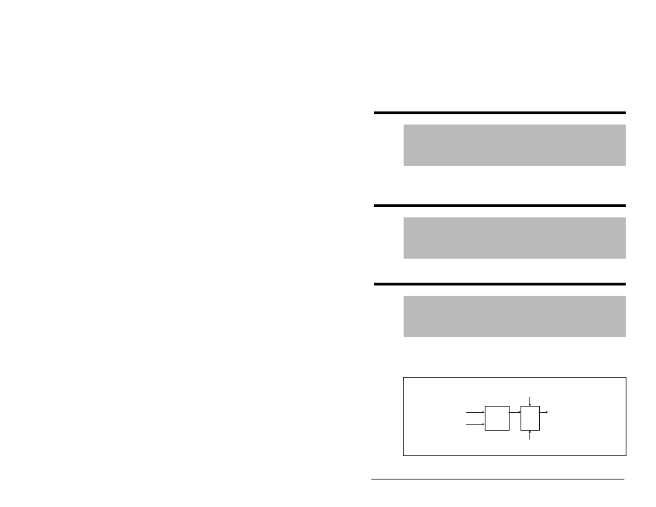
Figure 12.53 – Dig Out1 OffTime (383)
Comparator
Delay
Timer
Output
Frequency
(380)
Dig Out1
Level (381)
Dig Out1
OnTime
(382)
Relay Out1
(Term 11, 12, 13)
Dig Out1
OffTime
(383)